
|
| HOME What's New
Camera Stuff
|
|
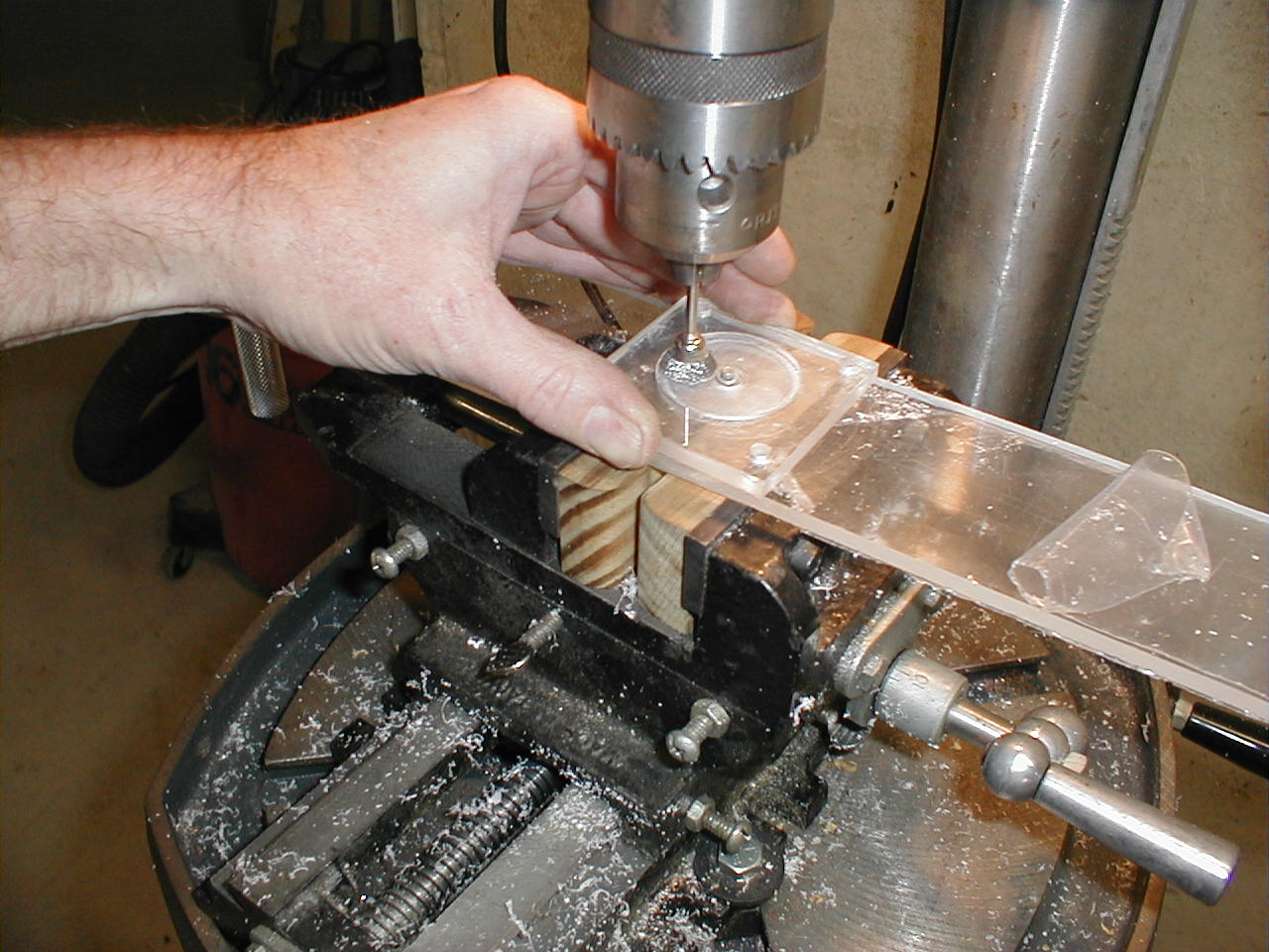 |
After
laying out the parts in AutoCad, cutting the patterns, and transferring
the patterns to the acrylic, I began cutting and milling the
parts. The first of the tricky cuts was the stepper motor
mount. "Tricky" is relative, but trying to mill on a drill press
is tricky! To get the recessed circle routed out of the acrylic, I used a shaft that was the same size as the hole in the center of the mount and rotated the part around the shaft. The second piece of acrylic below the motor mount was rotated along with the mount to prevent scratches on the bottom of the motor mount. This piece turned out almost perfect with the raised step on the stepper motor fitting snugly into the recess on the mount. |
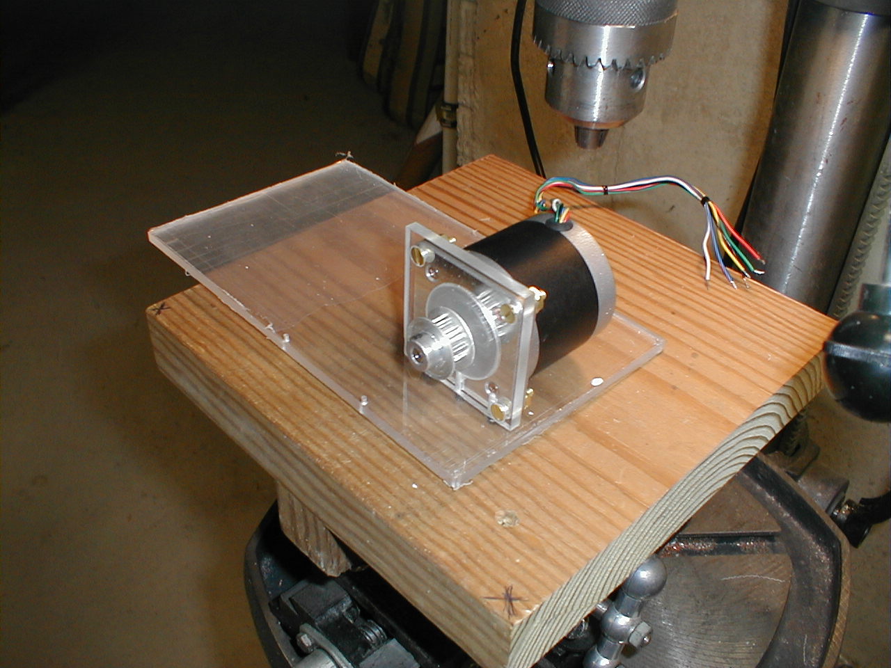 |
Here,
the motor is attached to the mount and the mount is attached to the
base of the tilting camera mount. While it looks like the base of
the camera housing is way too wide, the piece will be cut after the
left-most of the three holes in the front of the base. I assembled each new piece as soon as it was finished not only to make sure that the parts fit, but also to admire my work. ;-) This was a fun project to build and I was in no rush to finish it. |
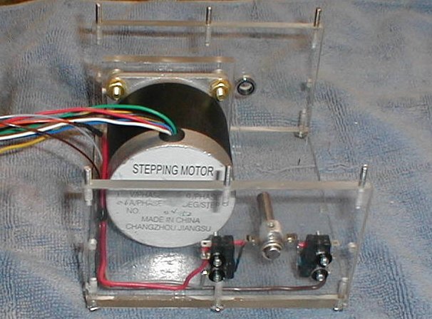 |
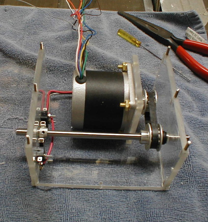
Four
pieces done. The1/4" by 3/8"
flanged
bearings are visible in both end pieces. In the foreground of the picture, you can see a stub of an axle with a hand ground cam lobe that actuates the roller equipped micro-switches. These switches are adjustable with a total of about 1/4" of travel. They are used to limit the amount of total tilt that the camera will be allowed to move. The cam lobe is also adjustable by means of a set screw in the center of the lobe. The hole is smaller in diameter than the roller on the micro-switch, so the roller glides right over the hole. I must have spent a half hour envisioning how the unit would tilt before I was sure that the switches were wired correctly. |
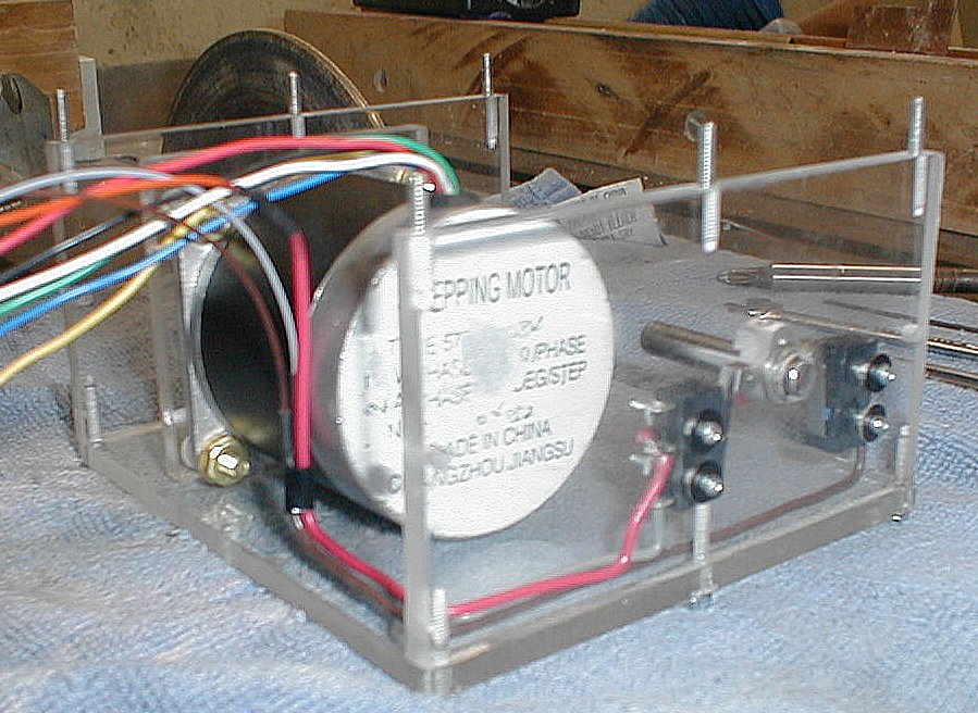 |
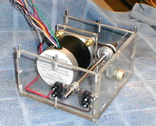
Another
shot of the cam lobe and micro-switches. The height of the cam
lobe is easier to see in this shot. The black washers are rubber coated to seal the oval adjustment holes for the switches. The bearings also have plastic seals and I packed the bearings with silicone grease to make sure that water could not enter the housing. Even though the camera will be placed under the eaves of the house, we get violent storms in the summer and horizontal rain is not that uncommon. Hopefully I will get a year or so of service from the tilt and pan mount before it will need to have the bearings repacked with silicone grease. |
 |
The
first critical test of my measuring, cutting and drilling came when I
installed the pulleys and toothed belt. I ended up with
deflection of between an eighth to a quarter of an inch. Perfect. It pays to, as the saying goes, measure twice and cut once. If there had been a problem with the belt being too tight or too loose, I would have just needed to recut the bottom plate. Not too time consuming, but nice that it fit right the first time. At this point in the assembly, with the motor offset quite a way from the axel shaft, it seems hardly possible that I have calculated the weights properly so that the camera and housing will balance perfectly on the axel, but I will have to trust that my calculations are correct as I won't be able to check it until the camera is mounted. At least I know that the distance between the motor and shaft was right, so the chances that the rest of the equation will work is on track. |
 |
The
front plate of the tilt housing is mounted. The camera is mounted
a bit below the center of the plate, on the same plane as the motor and
axel shafts. While the stepper motor sits flush with the floor of the housing, there is about 3/8" of space above it, between the top of the motor and the bottom of the top housing plate. This is to allow for the wires coming out of the stepper motor. I haven't mentioned it, but the lateral play in the axel shaft is adjusted with axel shims from an Associated RC-10 radio controled car. Both the pulley and cam lobe for the limit switches have set screws to hold them securely and the shims go between the pulley / lobe and bearing. The bearings are flanged with the flange to the inside. |
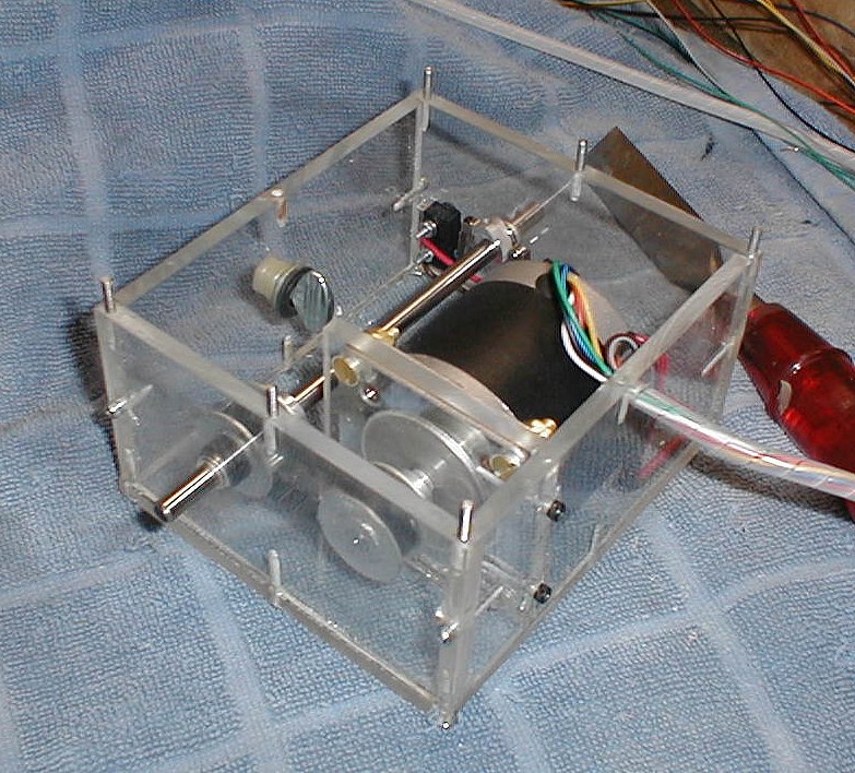 |
The
rear plate gets attached. The hole at the top for the 6 motor
wires, 3 limit wires, and eventually another 3 microphone wires in a
shielded cable and the composite camera power and video feed wires will
all come from the rear of the camera housing and terminate in the box
that will hold the pan assembly. The chisel with the red plastic handle is about 40 years old. It was one of my dad's tools and now a cherished one of mine. It still holds a great edge after decades of being honed on an oil stone and deburred on a leather strap. It is also a great tool for shaving small bits of plastic to make sure that the plates filt together perfectly. Once the entire tilt housing has been assembled and checked for fit, it will be sealed with a special acrylic adhesive that is as thin as water and applied with a syringe with a fine needle. The adhesive will |
 |
be
"wicked" up between the joints similar to a "sweat joint" when
soldering plumbing. I didn't have a lot of experience with this,
so I used many of the scraps of acrylic that I accumulated to
practice. This adhesive is really thin! It also leaves
visible traces of itself any place it comes in contact with. The
adhesive works by softening up the acrylic and needs perfectly mated
joints and some pressure to work. I'm glad that I took the time to do some research on "gluing acrylic" before I tried it, as I am sure that I would have ruined the parts if I hadn't practiced first. You can find a lot of information on working with acrylics by searching for acrylic diy build aquarium. |
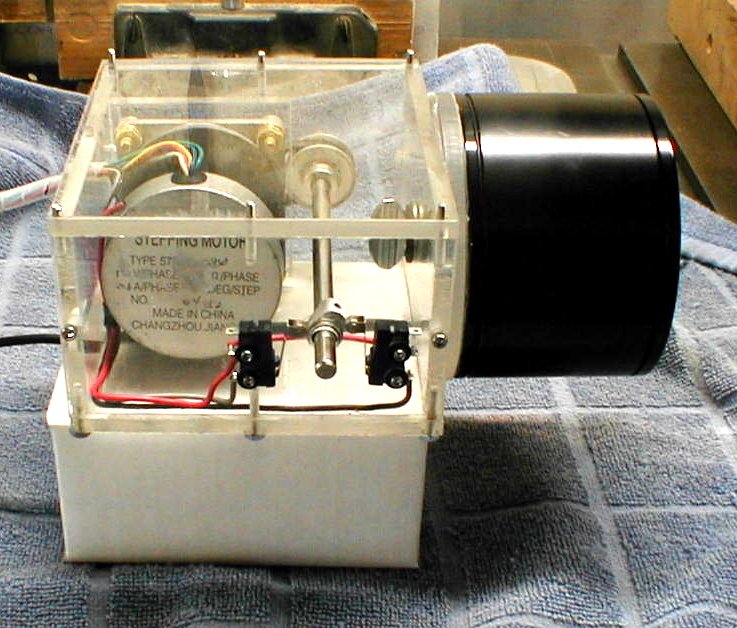 |
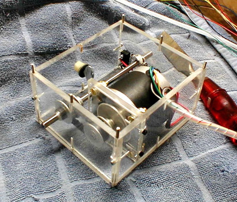
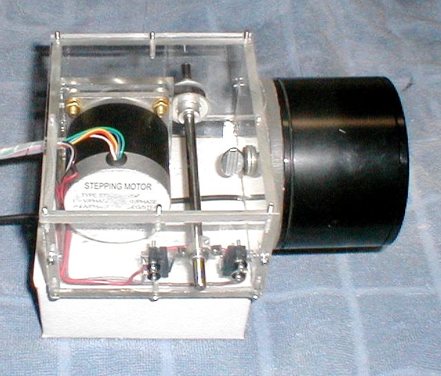
Finally
I get to put the top plate and the camera on to check for
fit. It fits pretty well. The round plate behind the camera is there to give me some additional weight in the front to help balance the tilt housing and camera. I have figured the balance point almost perfectly. With the plate in place, it is a little heavy on the camera end. If I remove the plate, it changes to be a little heavy toward the rear. Once I mount the microphone plate, I won't need the acrylic disk and the balance should be close enough that the force of the permanent magnets in the stepper motor will hold the camera and tilt housing at whatever angle I need. The thumb screw that holds the camera in place will allow me to make sure that the camera is positioned properly and then cinch it down. |
 |
Tonight
I hooked the camera up to the A06 controller and ran through a few
commands to make sure that the limit switches were doing their job
properly. I had to adjust them both a little to get them to allow
the desired 135° of movement. The camera will be mounted under the eaves of the second story of our home, above the front door. I would like for the camera to be able to look straight down so that I can see who is at the door. The upward angle should be enough to see over the tree in the front yard and on to the horizon beyond and the line of trees that is at the end of its line of sight. That should be handy for seeing weather related information such as the trees swaying or rain and snow hitting the leaves or branches. In the summer, I will be able to view the driveway and sidewalk, but a lot of the front yard will be obscured by the large flowering plum tree. In the |
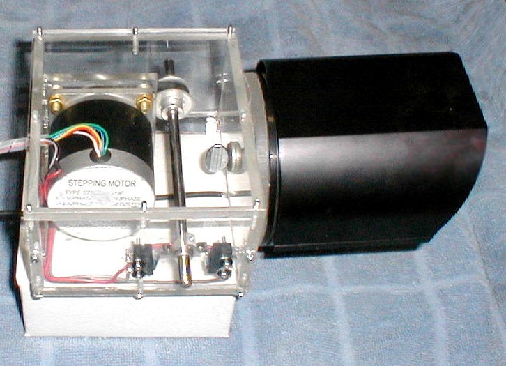 |
winter,
I should be able to view almost the entire front yard due to the leaves
being gone from the tree. The sun shade is test fit on the camera. It is made from a light weight plastic extrusion and doesn't add much weight to the setup. This evening I spent about an hour and glued up the tilt housing. It went pretty well with just a couple of places where the acrylic adhesive got on places where I didn't want it. I buffed these out the best I could and unless you are really looking for them, you wouldn't see them. Time to move on to the pan assembly. |
|
|
|
|
|
|
|
|
© Fager 7-31-05