
|
| HOME What's New
Camera Stuff
|
|
 |
With the
tilt housing essentially done, I turned my focus to the bracket that
would hold it. This was cut from some 1/4" X 2" aluminum flat
stock that I had from the days of playing with water cooled and peltier
assisted cooling for computer processors. I drilled a 0.250 hole
through 2 pieces of stock and temporarily held them together by forcing
a 1/4" brass tube through them. This allowed me to shape both
pieces at once and keep them pretty near identical. |
 |
Here I have rounded the corners
with the 10 inch disk sander attachment for my table saw. That
sander is a time saver. |
 |
After cutting the base and
drilling and tapping a couple of 4-40 holes, I took the pieces
out to the buffing wheel and polished up the aluminum. It never
ceases to amaze me how much of a shine you can get from polished
aluminum. I added 5 ore holes in the base for the 0.2502" shaft and coupling. |
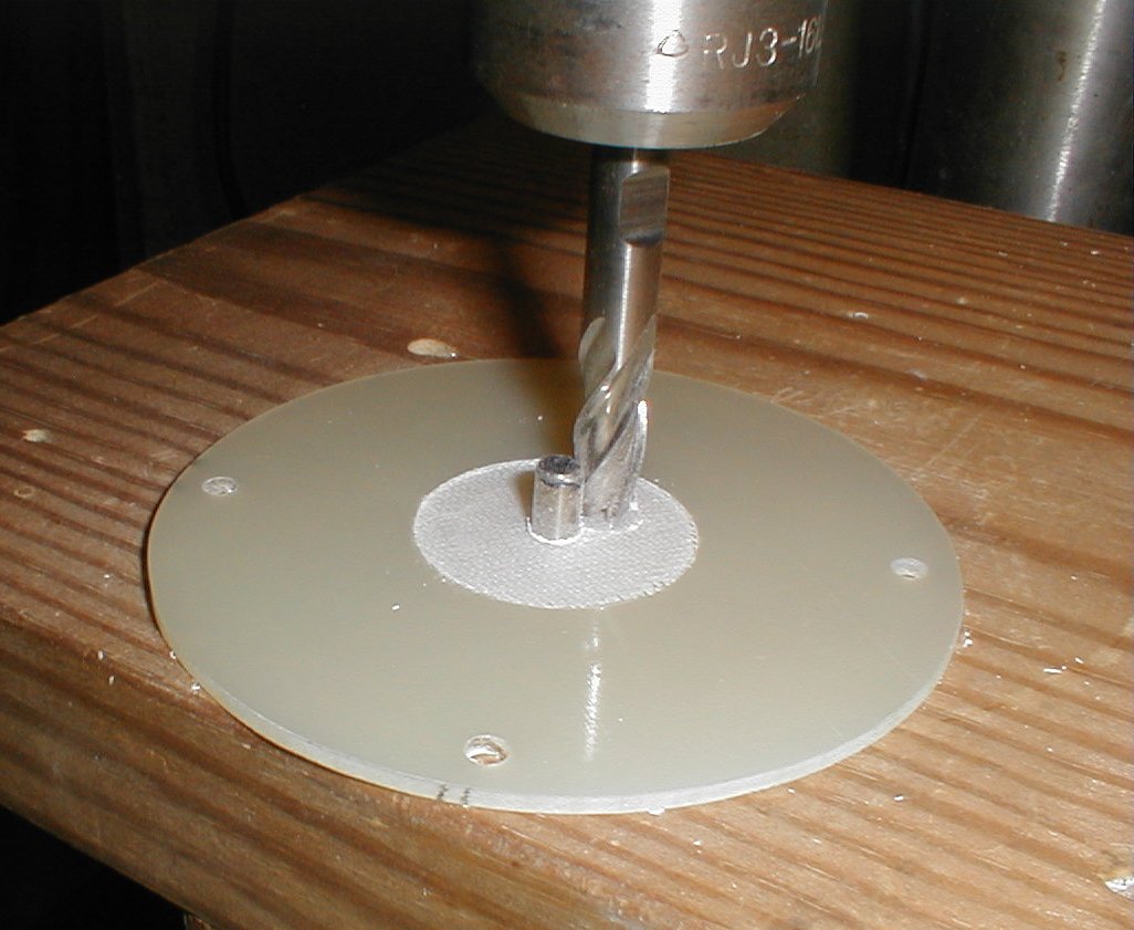 |
Time to get started on the "Pan" housing that will allow the camera to
rotate from left to right. I had found that using "all-thread" or
all threaded rod and stacking plates was the easiest way to build a
modular assembly. Using a couple of nuts to lock each layer in
position allows for an infinitely adjustable housing. This is
really helpful when you are designing as you go and are not sure of the
final dimensions. The first cut was for the stepper motor. |
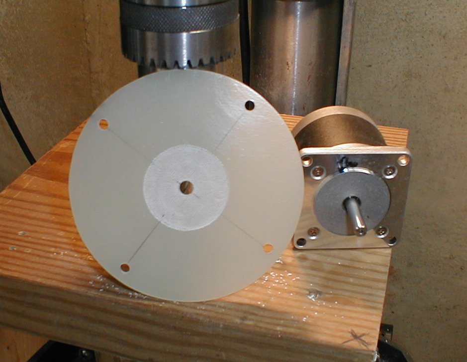 |
The "next to top" plate is finished. The left lower hole is a
little off, but still usable. |
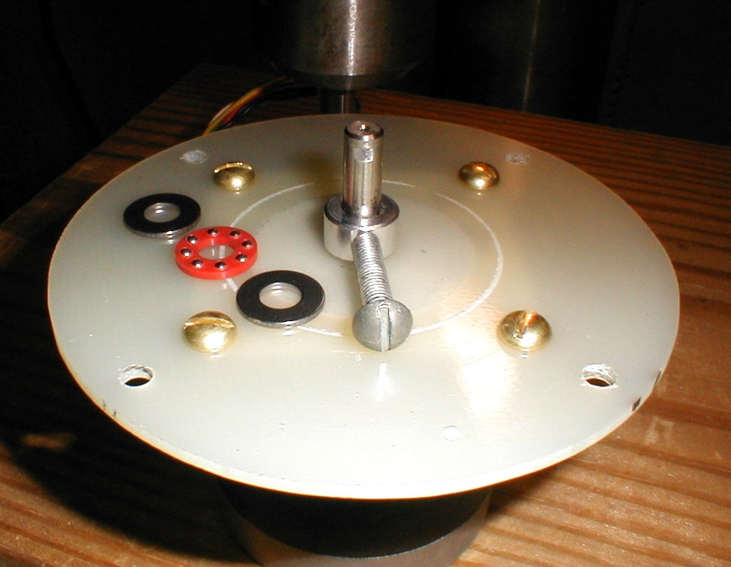 |
The
collar with the screw will turn the limit switches on and off.
The two washers and red bearing will hold the weight of the tilt
assembly and camera and allow it to rotate smoothly. |
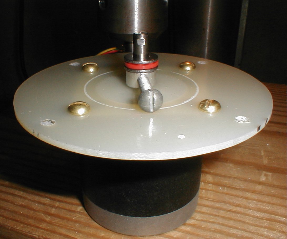 |
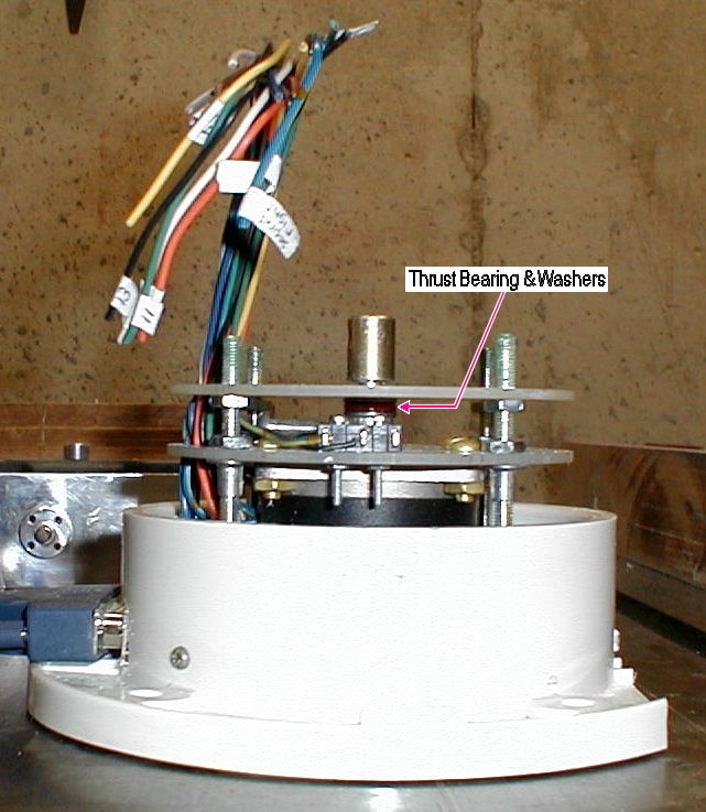
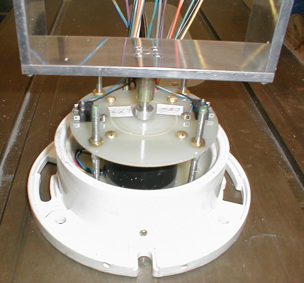
Here is a shot of the thrust
bearing temporarily installed. The top plate will go above the
bearing. You can see the "flats" I filed in the shaft that will
give the set screw a place to cinch against. |
 |
Here the all-thread has been installed, along with the limit switches
and the stepper motor. The further away from the center shaft that the switches are mounted, the more and finer adjustments that can be made on the limit switches. A small cam lobe would have made for a nicer looking setup, but the long screw allows me to position the stop switches more accurately. |
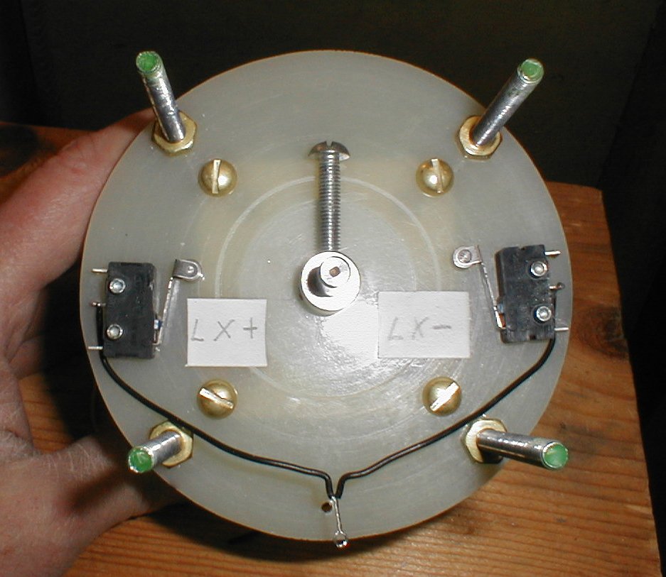 |
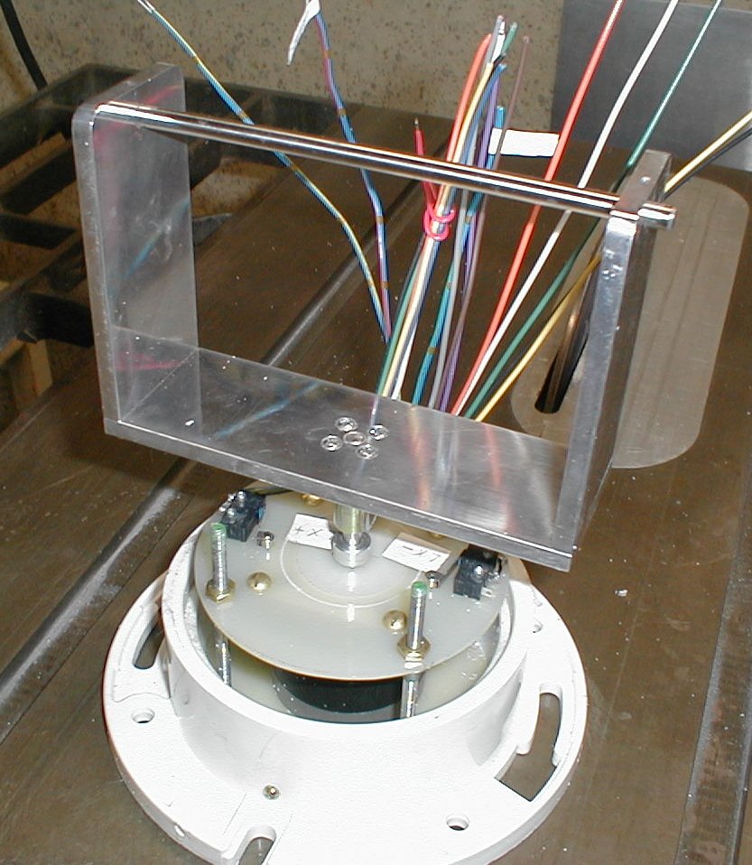
Here's the top view. It's not shown here, but I ended up flipping the position of the switches after I got the pan assembly finished. Once they were flipped over, it gave me about 200° of rotation before the limit switches would stop the camera from turning. |
 |
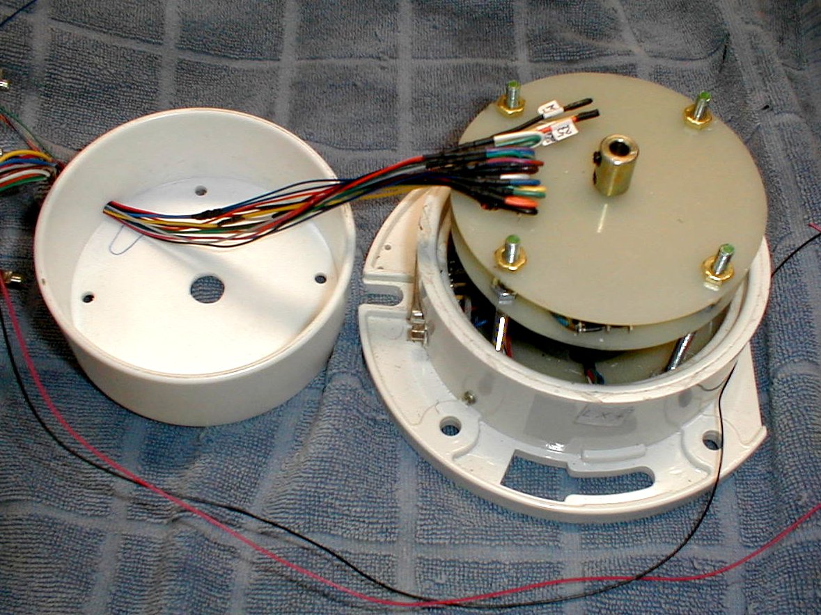
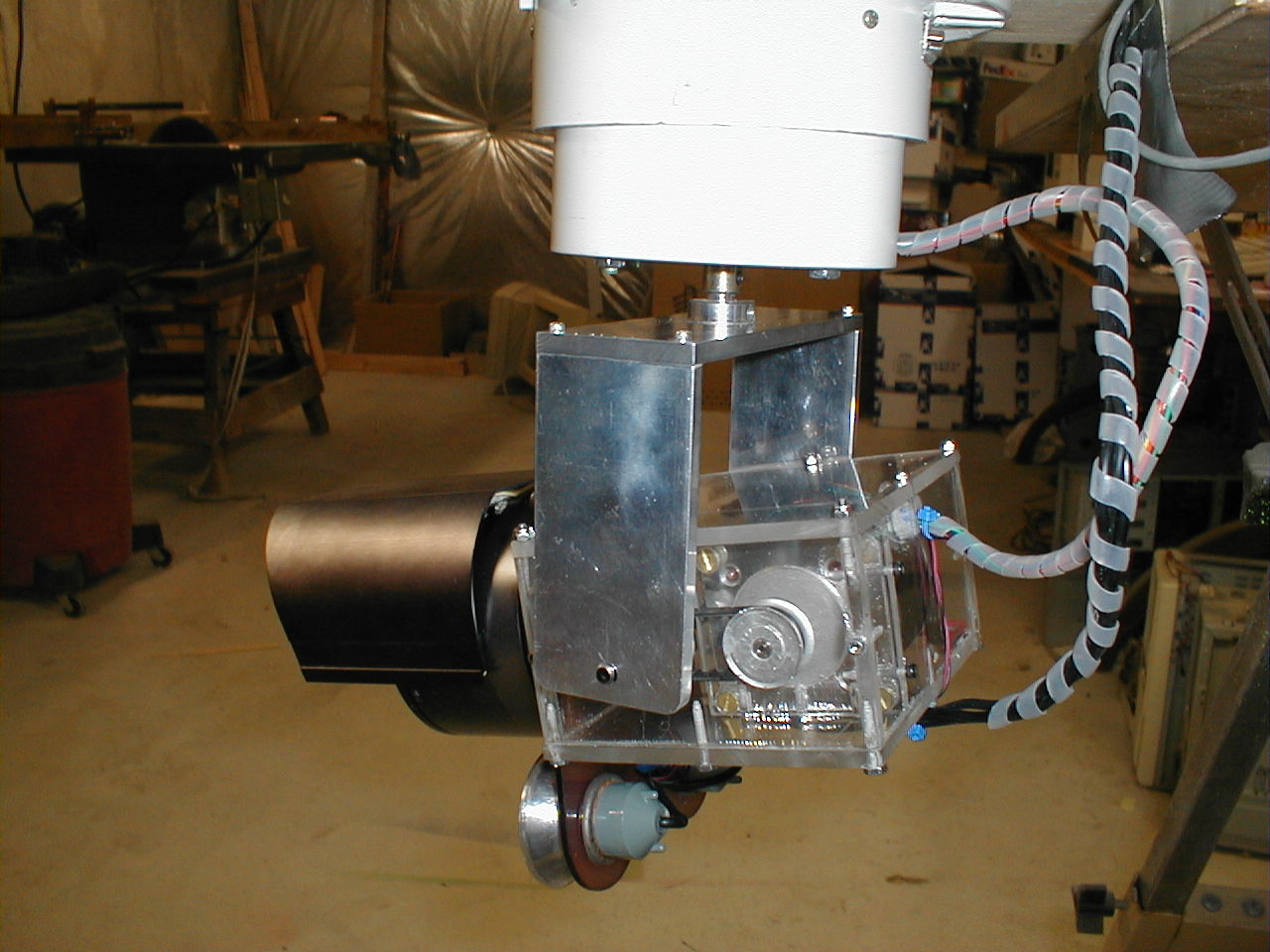
Now you can see the position of the thrust washer. If you imagine
the whole assembly turned upside-down, you can imagine how the thrust
bearing will hold the weight of the camera and tilt assembly. It
is not a large bearing, but the action of turning the camera is quite
smooth. The thrust bearing also saves the motor bearings from
having to take any vertical forces. There are quite a few wires that needed to be attached here. If you look at the lower right of the white plumbing flange (for holding toilets, no less!), you can see the side of a parallel port connector. Of the 25 possible connections on the connector, I used 22 of them. Numbering the wires was a must. |
 |
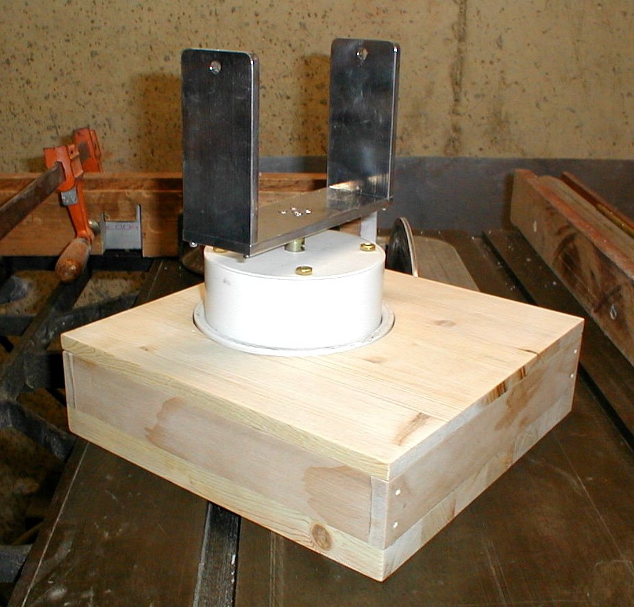
Here, another plumbing supply is used as the cap for the pan
assembly. The coupler visible on the top plate just protrudes
through the cap. Before the camera went outside, I fitted a seal to the end cap to prevent moisture from entering past the coupling. I also used silicone sealer on the mating surfaces. While it was not water-proof, it is pretty weather-proof. We had a couple of "gully-washer" rain storms after I had the camera mounted under the eaves of the house. I pulled the camera and checked for leaks. I was happy to see that there were none. |
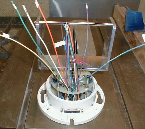 |
A shot of the tilt bracket being test fit. The 25 pin connector
is plainly visible in this shot. |
 |
Another view. |
 |
Last chance to adjust things before the cap goes on. Time to do
some more soldering. |
 |
The cap goes on after all the wires have been soldered and
routed. A plug is test fit to make sure that all is well before
using some silicone to seal up the connector. |
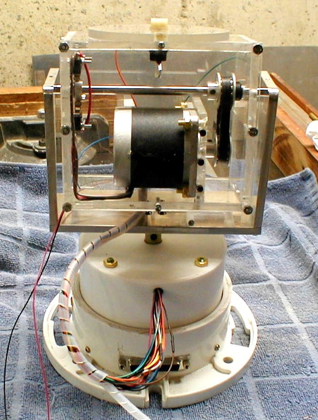 |
The tilt assembly gets fit and wired up. Rubber grommets will be
used where the wires enter the housings. Some cable wrap is used
to bundle up the wires a bit. The two thin wires will be used to turn on an off a relay that I installed inside the camera. This allows me to turn on and off the 104 infrared LEDs. The relay only consumes about 10 milliamp, so the wires don't need to conduct much current. |
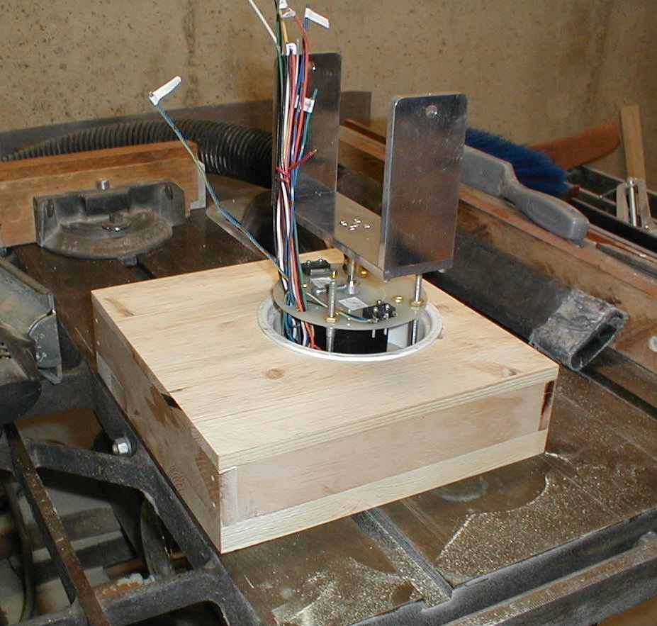 |
To weather-proof the pan assembly, the whole thing is places inside a
wooden box. Cutting fiberglass, then using the same blade to cut
wood results in a poor cut. You can see the heat marks.
Since I was just painting the box with some house paint, I wasn't too
concerned, but I really should have switched to a fresh blade for the
woodworking. I think that's called lazy! Yes, this picture is out of order in terms of when the box was built, but made more sense when trying to give some order to the project. |
 |
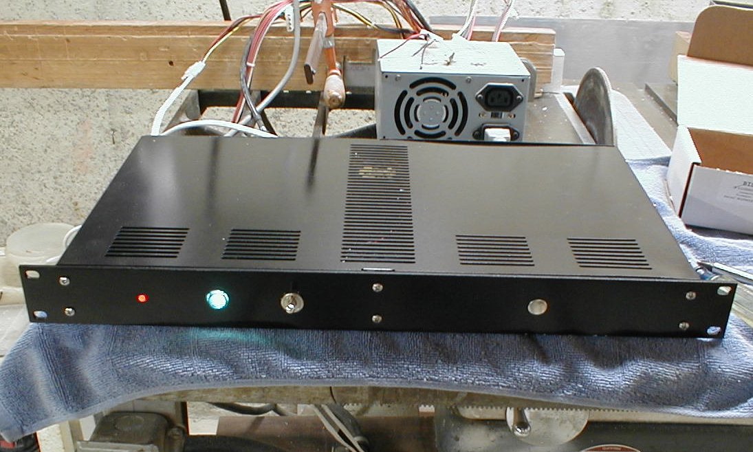
A shot of an almost complete project. A little paint, and .... |
 |
One
last shot before painting. |
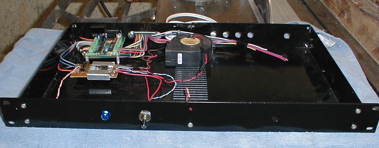 |
An early shot of the stepperboard controller after installing it in the
little 1U rack case.. |
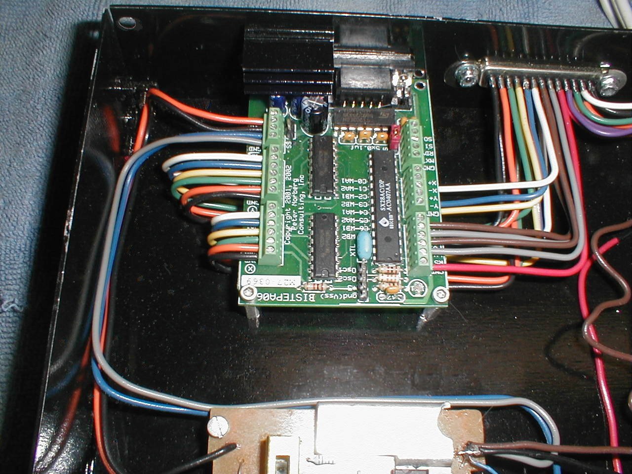 |
A closer view of the stepperboard Bi-Step A06 controller. You can
get the board with the screw terminals or pin-type connectors. I
chose the screw connectors. The wire is 12 gage solid
copper. There is not much voltage drop between the board and
tilt-pan assembly. |
 |
Here is a shot of testing the LEDs on the 1U case using an old AT type
power supply. I used my Rivergate Bulldog 30
amp power supply once I got everything mounted. The Bulldog
is way more powerful than needed, but fulfills the requirement of a
linear power supply that the stepperboard needs to operate
correctly. I eventually purchased a 6 amp linear supply to
dedicate to the camera so I could return the Bulldog to its place on
the test bench. The stepper motors only draw a couple amps total,
so the 6 amp supply doesn't have to work very hard to supply the motors. |
 |
Between the 4U computer and the SCSI array, you should just be able to
make out the 1U stepper controller and preamplifier. Below the
rack cases are the old Linux boxes. The left one is the test box
with the software that controls the tilt-pan camera. The right
one is my connection to the web, file server and also runs software to
detect motion on the camera and save the movies without sound. |
 |
This is the last shot of the
camera and tilt-pan assembly before it got painted and moved
outside. You can see the microphone(s) under the camera. |
I actually finished
this camera a couple of months ago. Once I had it mounted
outside, I worked on a program to interface the tilt and pan functions
with the Motion
software. I also set up a web page where I can manually control
the camera by clicking on the side of the image that I want the camera
to move to. I also incorporated about a dozen "presets" so that I
can push a button and the camera will move to a pre-determined
location. I also added two buttons that control a sequence that
pans the camera slowly up and down the yard and driveway, then stops at
its home, which is the end of our driveway.
After playing with the
camera for a while, I decided that I didn't like the stepper
motors as much as I thought I would. Over the course of two
weeks, I designed and built another tilt and pan prototype using a
couple of very large 1/4 scale servos for controlling 1/4 scale radio
controlled airplanes. I am MUCH more impressed with the
performance of the servos than the steppers. The main reason is
weight. Steppers are heavy and the mass of the camera, housing,
bracket, and stepper adds up to a substantial amount. It takes a
bit of time to get all of that mass moving and it also take some time
to stop it. This make it hard to follow quick movements, like a
rabbit or squirrel running across the property. Once I changed
over to servo motors and built a tilt pan controller that was about 1/3
the weight of this project, I started to get much better tracking
ability. I am in the process of designing the third tilt-pan
assembly and am hopeful that this one will do everything that I need it
to do.
I have also had enough of
using the wrong tool for the job. Trying to use a drill press for
a milling machine is an exercise in frustration. After wanting
one for years and researching what to buy for months, I have purchased
a mill. As I write this, I am waiting for the trucking company to
call and let me know that they have my new toy. This should
finally allow me to build what I can draw.
|
|
|
|
|
|
|
|
© Fager 7-31-05