Tilt/Pan
Camera Mount
September 14, 2005
Getting Started
(I can't believe that I have been working on this project for a year. Besides the normal interruptions, I have had a couple of surgeries on my sinuses that slowed me down a bit.)
This project started back in August of
2004 when I got the urge to buy a video camera. I think I had
seen
some security cameras at Costco for about $1000 and thought that "I
could do that." As
I began researching cameras, I started thinking about my requirements
and what I would like to
do with the camera. Since our son, Michael, is about to start his
third year of college, Susie and I have the opportunity to do more
traveling. The idea of being able to keep track of our
house and property with a video camera on the web is something that
I've thought about for a long time.
Flash back to me being about age 10 and my folks
were looking at new homes. I was thoroughly amazed by the "then
new"
intercoms that were cropping up on the model homes of the 1960's
era.
Pretty neat stuff for the time. With the intercom, you could talk
to whomever was at the door, or talk to dad in the basement, or the
kids
in their rooms. You could even pipe music throughout the
house. Forget the fact that these houses were only about 2000
square feet and
you could probably talk loudly and be heard as easily. I was
impressed
at the technology none the less. From
that time on, my interest in home automation grew.
Over the years I have done a few intercoms, but nothing too
exciting.
Now I had gotten the home automation bug again and it was time to see
where this would lead me.
Looking for a camera was quite a
task.
The number of cameras on the market is staggering. You can spend
as
low as $25 and top $2000 quite easily without even venturing into the
professional end of the market. As this was my first
security
camera and I had little idea of where I wanted to take this project, I
limited my spending on my first camera to under $300 with the thoughts
that if this was something that I wanted to get serious about, I could
easily replace the camera. So far, twelve months into the
project, I
have
not felt a need to jump to the next level of camera - though I may be
getting close.
My
original camera requirements were just that the camera be able to watch
the front
of my home - from the street to the front door. This meant
getting a security camera with
a
tilt/pan/zoom (PTZ) assembly. PTZ can be performed from a
dedicated controller or through the computer. The computer was
the obvious choice for me. Having the camera and PTZ computer
interface would allow me to be able to view and control
the camera's view from the Internet. This would be nice for
checking out the house while on trips. As I continued
to research suitable cameras, I found that the ability to "see at
night"
was well within my price range, but that a weatherproof tilt/pan/zoom
was
going to be the costly part of the equation.
After finding a camera that allowed
viewing
color by day and black and white with infrared assist at night, (the
104 LED color camera), I decided that rather than buy a tilt and
pan device, I would try my hand at building one. We'll get back
to this a little later. The camera I purchased is a pretty fair
quality
unit with a 25 mm fixed lens. To put this lens in perspective, a
6 mm lens is supposed to be about what your eyes would see, so 25 mm is
a close-up or telephoto lens. (They have a
pretty good
example
of different lens options and the field of view from each here.)
Since this is a fixed lens, the zoom "requirement" was something I
wouldn't have to
deal
with on this camera, but at some point, I would like to either buy or
make one.
Image Sensors
 The cameras I looked at used either a
CCD (Charge-Coupled Device) or CMOS (Complimentary Metal Oxide
Semiconductor) image sensors. There was a time in the not to
distant
past when the CCD image sensor was the sensor of choice. Now,
both the CCD and
the CMOS chips are found in quality cameras, with the CMOS chip being
used in cameras such as the $5000 Nikon D2X. In the security camera
market, there seems to be more of the CCD chipped cameras in the mid to
high quality range, though the CMOS cameras are getting better and are
less costly to produce. This is mainly due to the fact that the
CMOS sensors can be manufactured in the same "fabs" (chip fabricating
facilities) as for other integrated circuits, like memory. The
CCD sensors use a totally different manufacturing process not shared by
ICs.
The cameras I looked at used either a
CCD (Charge-Coupled Device) or CMOS (Complimentary Metal Oxide
Semiconductor) image sensors. There was a time in the not to
distant
past when the CCD image sensor was the sensor of choice. Now,
both the CCD and
the CMOS chips are found in quality cameras, with the CMOS chip being
used in cameras such as the $5000 Nikon D2X. In the security camera
market, there seems to be more of the CCD chipped cameras in the mid to
high quality range, though the CMOS cameras are getting better and are
less costly to produce. This is mainly due to the fact that the
CMOS sensors can be manufactured in the same "fabs" (chip fabricating
facilities) as for other integrated circuits, like memory. The
CCD sensors use a totally different manufacturing process not shared by
ICs.
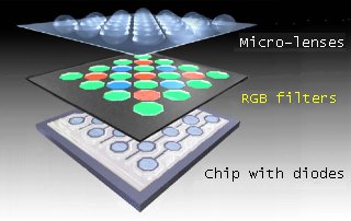
The Sony Super HAD
(Hole-Accumulation Diode) CCD that comes with the camera I purchased is
an improvement on previous on-chip microlens designs found in many
security type cameras. The on-chip
microlens has one lens for each of the diodes (also called photosites)
that change light into electrons. Sony has been able to reduce
the amount of "wasted" light by changing the lens shape and
reducing the distance between the lenses. More information on the
Super HAD CCD may be found here.
Sony now offers what they call the EXview series of HAD CCD chip with
enhanced infrared (IR) capabilities.
IR and the ability to see in darkness
has
always been fascinating to me. The ability to see when
it is dark is definitely an advantage when thinking about home
security. The image sensors
start by
converting light into electrons at the photosites on the sensor. With
the addition of red, green, and blue filters (additive color system) or
cyan, magenta, and yellow filters (subtractive color) for each of the
photosites, they are able to produce color images. However, being
able to produce color images has it's cost. The filters cut down
on the available light that hits the
photosite so that a color camera has less sensitivity than a black and
white camera using the same image sensor. In addition,
because a color camera must dedicate photosites for each of the three
colors used to produce a single pixel in the image, the resolution of a
color camera is less than that of a black and white camera using
the same image sensor.
Throwing "night vision" into the mix is
easy. Unfiltered photosites (black and white image sensors) are
not only sensitive to the range of visible light, but are also
sensitive to the near infrared range. Some chips are better than
others for this and the day night camera I purchased is happy to
produce images using light in the 940 nanometer range. In case
you've forgotten your electromagnetic wavelengths, they are
(approximately): below 400 nm = ultraviolet, 470 nm = blue,
570 nm = yellow, 670 nm = red, above 700 nm =
infrared. The low 700s range of infrared is still somewhat
visible as a dull red glow, but 940 is completely invisible to the
human eye. With the 104 LEDs producing infrared energy, the
camera
has a night time range up to about 60 feet (~20 m) with pretty good
brightness and tails off from there. While testing how well the
camera picks up IR light, I purchased a couple of
high intensity, infrared LEDs from Radio Shack and wired them into a 2
cell flashlight. It produces a nice little beam that can be seen
by the camera, but not by me or passers-by. I'm sure the
neighbors think I'm nuts when I'm out in the street, in the camera's
view, playing with what looks
like a non-working flashlight. Maybe this just confirms my "nuts"
status.
Anyway, I am having fun playing with
IR. I have recently purchased 500 IR LEDs and have some ideas for
wiring
these up beside some low voltage outdoor garden lamps. If this
project works as expected, I will be able to run the visible light if
guests are coming over or we will be returning home late. Once
it's
time to secure up the house, I'll be able to shut off the visible light
and crank up the IR and let the camera watch the property as I
sleep. This sounds like a good plan, but I'm getting ahead of
myself and need to get the
tilt and pan built first.
There are two accepted ways to approach
moving
the camera on a tilt/pan assembly. The first is using
servo
motors. Servo motors work by placing an encoder
in line with the motor output shaft. This way, there is a known
encoder position
for every location the motor can turn to. It is possible to accurately
move the motor to the same location time after time. Servos are
common
in the radio control modeling world and because of this, there are many
moderate cost controllers and servos available. A standard servo,
similar to
the Futaba
S3003 can be had for about $US10. The down-side as far
as
my application was concerned was I *knew* them and wanted to learn
about stepper motors. So, even
though I
am much more
familiar with servo motors, I ended up using stepper motors. As
it turned out, I did learn quite a bit about steppers and found out
first-hand the positive and negative aspects of using stepper motor
systems..
Stepper motors are permanent magnetic
motors that "step" or move one increment each time the controller gives
the motor one pulse. They don't require position feedback if run within
their limits. When stopped, they inherently hold their position.
This "holding their position without power" mode is usually called the
"detent hold" or detent holding ability. The magnetic field of the permanent magnets
hold the
motor in position when the power is removed from the coils. The
force that is needed to overcome the magnetic field can be surprisingly
strong. This detent torque will be quite useful in the holding
the view angle when using the tilt function of the setup.
Once you power up the controller, each
pulse of the controller sends current to the individual coils
of the motor.
By turning on and off the individual magnetic fields in a sequential
pattern, the motor turns. There is a good explanation of the
different stepping sequences here.
There are many ways of controlling stepper motors through a
computer. You can use a
software program to apply power through the parallel port to move
bipolar
and unipolar steppers. You may also program the stepping
sequences
into an electronic logic circuit and use switches, or the serial or USB
ports to
control the
stepper(s).
To start my learning about stepper
motors,
I dug through the "old parts" boxes in the basement workshop and came
up with a
couple of 5 1/4" floppy drives. I salvaged the steppers
from
these and played around with parallel programming for a couple weeks
until
I came to the conclusion that this wasn't the interface I was looking
for.
While I was researching different ways to control the steppers, I ran
across
a program that would focus my expectations of this project. The
program is called Motion. It is an open source project designed
to
detect motion from cameras. If you are interested, you can
read
all about Motion on the Motion
Twiki. I will be revisiting Motion once the hardware is
built,
but for now,
Motion
has some support for a serial and USB tilt and pan interface. In fact,
they have a schematic for a one axis pan controller.
After
some thoughts of building my own circuit for a serial interface, I
decided on a pre-built controller board from Stepperboard.com.
Stepperboard's BiStepA06
was the board that suited my project the best.
I ordered one and received the BiStepA06 a few days. I
mounted it
in a small project box with a circuit to drop the 12+ volts from my
power supply down to 9 for the logic circuit of the stepperboard and a
couple LEDs.
The BiStepA06's circuitry then drops it to 5 volts. The motor
circuits run on the
full 12+ volts from the power supply. I also added a small fan to
keep the chips from getting too hot. I spent the next week
playing with C programming and serial ports until I had a basic program
to allow my Linux box to talk to the stepperboard. This time was
pretty uneventful until the stepperboard stopped working one day.
An email or two later, I packed up the board and shipped it back to the
manufacturer. It turned out that I may have killed it by static
discharge (but I don't think so). However, Peter replaced the bad
parts and shipped the repaired board back quickly and for just the cost
of quick shipping that I requested. I was pleased with the
treatment I received and would not hesitate to recommend the product.
So with the board back
and the basic
program for controlling the
steppers written, it was time to order the mechanicals that would make
up the tilt and pan device. I went to Jameco for the stepper
motors and purchased a pair of 6000 gram-cm holding torque 12 volt
steppers. These are a bit on the "overkill" side, but having more
power than I need is preferable to going the other way. I also
hit Stock Drive
Components for some timing pulleys, shafts, belts,
thrust washers, collars and flanges. These were quite expensive
for what they were and I had some issues with their ordering software
while trying to place my order. Finally, to end my dealings with
them, the order was late in arriving
and when
it arrived, it was packed extremely well in heavy cardboard with wooden
ends, with not a bit of damage on the outside of the box, but the 1/4"
diameter steel shaft that I ordered was bent. This meant it
had to be bent when
they packed it. After spending almost $100 in parts, I expected
better treatment. While Stock Drive is one of the largest
companys for gears,
pulleys, and other miniature drive components, I think I will try to
look elsewhere next time I need to order.
The last order I placed was for some
ball bearings to ease the friction
a bit in the tilt housing. I ended up getting these at Tower Hobbies
and purchased 10
for the price of 2 at Stock Drive. These 1/4" by 3/8" flanged
bearings happen to be the same as used on a couple of radio control
cars I own, so I was familiar with the part and knew that Tower would
have a fair price for them.
The last item on the list was what to make
the assembly out of. I gave this a lot of thought and finally
decided on acrylic plastic for the tilt housing and wood and plumbing
supplies for the base and pan housing. Yes, I admit that it is a
strange combination, but that's me. I had
considered making the whole project from aluminum, but it would have
made for a lot more work under the drill press. Aluminum would be
nice if I decided to
make more of them, as I would have the housings cast and
machined. However
casting a one-off piece is expensive if you don't have the equipment to
do it yourself.
Prior to ordering my parts, I spent the better part of 2 weeks working
on the cad drawings for the
tilt assembly and a couple of days on the pan assembly. I had
been designing the tilt and pan device in my head for about a month now
and it was time to get the design on paper and work out the bugs.
I encountered some items
that needed consideration while
designing the tilt mechanism. First, the tilt housing with camera
attached had to balance with a camera that mounted from the rear rather
than the bottom like a normal camera. This is why I went with a
timing belt rather than direct drive. The timing belt allowed the
motor to be placed in the rear with the camera in front. The gear
ratio is still 1:1.
Secondly, the direction of rotation had to be accounted for so that
panning to the right and tilting upward were the same direction.
I first drew the plans backward and only through visualizing the
assembly in operation did I realize that I had the motor flipped the
wrong way to tilt up with a counter-clockwise rotation (when looking at
the front of the motor.) Yes, you can wire it backwards to make
it turn the opposite direction, but it's better to have it right to
begin with.
I made
templates for all of the acrylic pieces I needed and proceeded to cut,
drill, and tap each of the pieces. I have put together a pictorial of
the build process here. I have
tried to put it in some kind of logical order for viewing as the order
I built it in was often dictated by which one of the sub-projects I was
interested in on that particular day. It wasn't unusual for me to
work on a couple of different parts on the same evening. When I
was doing the drilling and tapping, I would have to take a break and
work on something that was more fun, then go back to drilling holes and
cutting threads. The holes had to be drilled as accurately as I
could get them, given the accuracy of my drill press. If a hole was off
by more than a couple hundredths of an inch, the piece would often have
to be scrapped. I ended up scrapping more than I would have liked
to. This usually happened when I got tired of drilling holes, so
I started drilling and tapping some holes in the beginning of the
evening and then moving on to another piece of the project after an
hour or so.
I had an empty 1U rack case that I
decided to use to hold the controller. As I was wiring up the
Stepperboard, I started thinking about
sound for the camera. My camera isn't equipped with a microphone,
much less stereo mics,
but I was thinking that it wouldn't be too hard to implement. I
was wrong.

© Fager
7-30-05
