
|
While we were
discussing what to do with my son's Ram truck with a case of the
death
wobbles, he had another car problem. His wife's recently
purchased, used, 2012 Jeep Wrangler Sport Unlimited 4 Door
started smoking from under the hood. My son, Mike, was able to
determine that it was the air conditioning compressor clutch
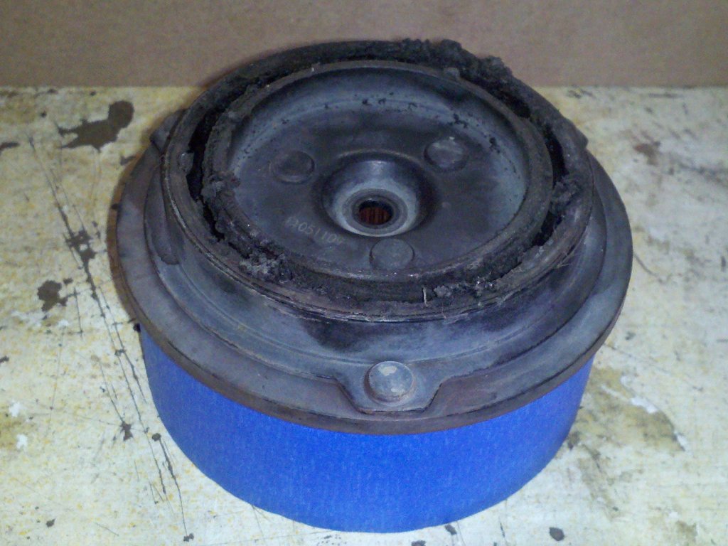
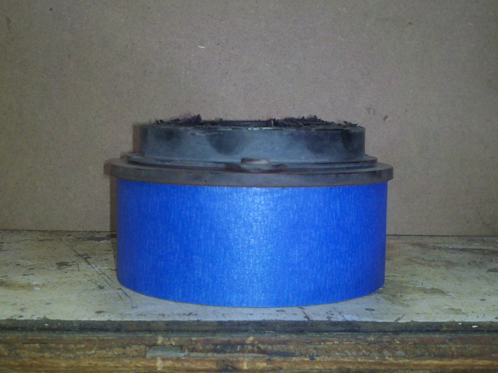
producing the smoke and shut off the AC. The rubber ring in the
clutch disk assembly had gotten so hot that it was smoldering.
It didn't catch fire, but I have since read of instances where
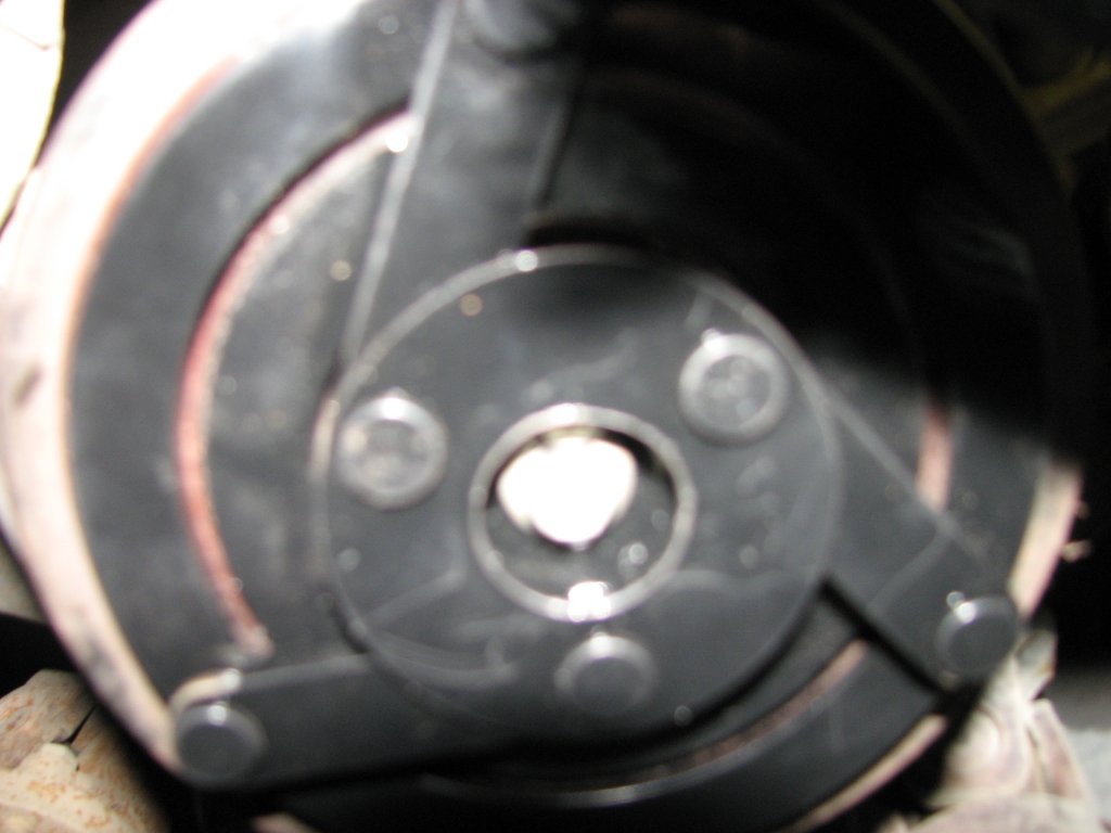
people said that theirs did. He sent me some pictures, but
they weren't too clear due to the compressor being hidden
beneath the top radiator hose.
He gave me a call and
we talked about the possibilities. I suggested that if the
compressor wasn't locked up, he might be able to just replace
the compressor clutch. He made some calls and later told me that
the dealer wanted over $800 parts and labor to replace the
compressor. The compressor alone was $510. Apparently, the
compressor clutch assembly doesn't come separately. I told him I
would look into it and see what we could do to drop the price a
bit. There's not a lot of info on this particular air
conditioning, but I read as much as I could find. There are a
half dozen sites that advertise that they carry a replacement
compressor that will fit the 2012 Jeep. There are also a few
Ebay sellers that list a replacement, but no one I found sells
just the compressor clutch.
I found a seller on
Ebay that had a compressor they said would work. Since they had
good reviews, I sent them an email with the Jeep's vehicle
identification number (VIN)
and asked if their compressor was a drop-in replacement. They
said yes and I ordered it. At just under $200 with shipping
included it seemed to be one of the better deals I had found. I
got the compressor quickly, it was a brand new Chinese made
compressor and it looked good. If it fit, we were in business.
We put it aside until we were ready to replace it.
 |
 |
|
|
|
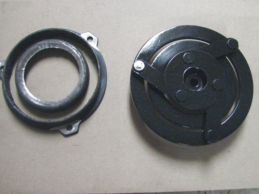
With the Dodge's death
wobbles cured, the day finally came to install the compressor on
the Jeep. We pulled enough parts off the Jeep to actually be
able to see the AC compressor clearly. This involved draining
the engine coolant and removing the top radiator hose and
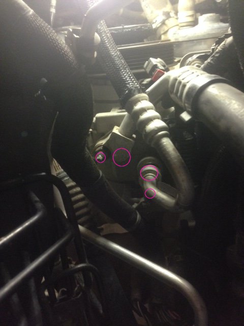
radiator overflow tank to gain some access to the compressor. I
got a better look at the compressor and noticed that we had some
issues. The electrical plug on the new compressor didn't match
the one in the Jeep. This was easy enough to fix, but the next
problem wasn't. The AC high and low pressure hoses have formed
aluminum connectors where they attach to the compressor. These
are formed in a manner that allows them to be installed in one
direction only. Each port on the compressor has a stud that
aligns the hose connector to the port. The studs on the
replacement compressor were in different positions than the ones
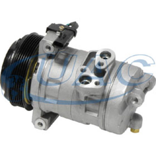
on the original. If you look at the picture above and the
picture of the replacement compressor below, you'll see that the
position of the studs on the original compressor don't match the
position of the stud holes on the replacement. I suppose that if
you really wanted to use the replacement, you could replace the
hoses, but that's a whole different can of worms. We'd need to
get hoses made up and I'd need to either hard wire the
compressor or cut out the waterproof socket on the old
compressor to replace the new one that didn't match. I might be
up for this on a 10 year old vehicle, but not on their
relatively new Jeep that was just out of its warranty. I decided
that I needed more info on the compressor so I could try and
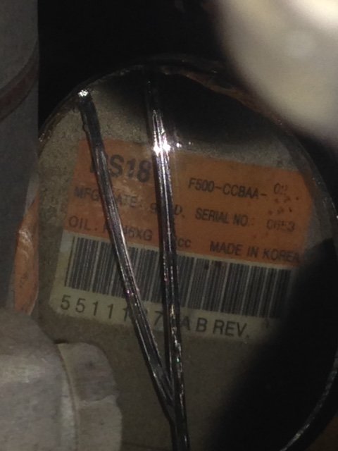
match it to a replacement. I got out an inspection mirror to see
if I could find the part number for the compressor. Here is the
info from the sticker I found underneath the compressor.
| Compressor
label -- the compressor number is 55111374AB |
As a last ditch effort, we measured the
clutch disk on the new compressor to see if we could swap it
with the old one. Unfortunately, both the size of the disk and
the splined mounting were different from the stock one. We
put the Jeep back together and Mike made the long trip back
home. Aside from getting to visit with my son, it was a wasted
day. I'd contact the Ebay seller and see what we could do to get
the proper compressor.
 |
 |
|
|
|
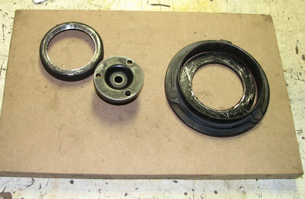
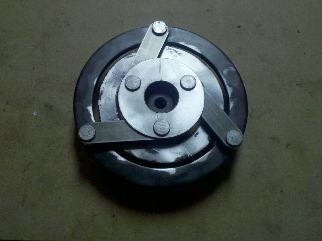
Having worked on a
lot of vehicle air conditioning systems, I was curious about
the change in compressor clutch design from when I was working
on them. All of the AC clutches I had ever seen worked the
same way. You flip the control on the dash to turn on the AC
and it energizes a coil on the compressor. The coil is an
electro-magnet. The magnetic force pulls the clutch plate,
which is attached to the compressor shaft with springs.
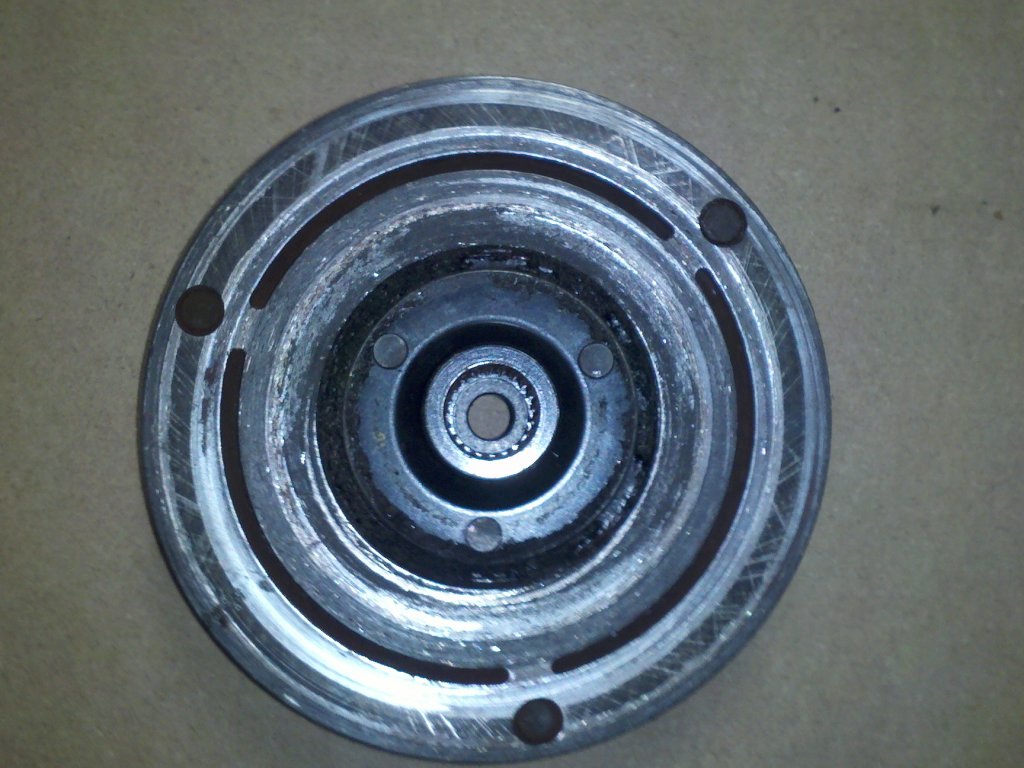
The clutch plate sticks to a machined area on the compressor
pulley. With the pulley and compressor shaft locked together
by magnetism, the compressor shaft is able to be turned by an
engine belt. The difference was that the old AC clutches used
three flat steel springs and this clutch used a ring shaped
piece of rubber as a spring. I am not sure why the change was
made, but my 2006 Dodge Ram also
has the rubber spring clutch. Most likely, it was a cost
cutting measure.
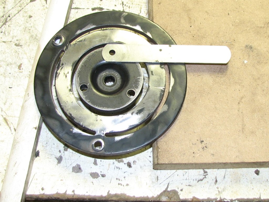
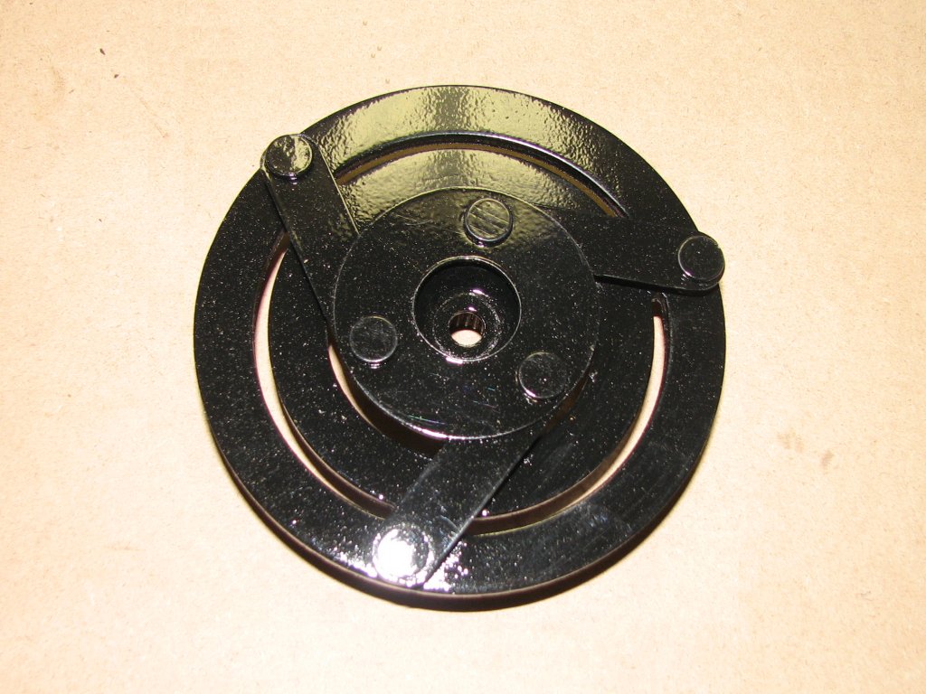
From the owner's
point of view, the change isn't a good one. With the old
system of metal springs, if the compressor clutch slipped, the
resulting wear would widen the gap between the clutch disk and
the pulley/clutch coil. If the gap got too wide, this would
prevent the clutch from engaging and you'd have no AC. To fix
it, you could reset the air gap between the clutch and pulley
by removing some shims from between the clutch hub and
compressor shaft. If you found ridges (signs of wear) on the
clutch plate, these could be dressed with a file to flatten
them out and you were back on the road with a working air
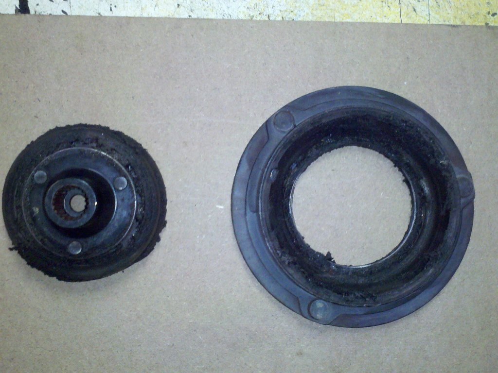
conditioner. With the rubber spring clutch, as soon as the
clutch starts slipping, the high temperatures (I read 1200° F
was possible in less than a minute of slipping.) could char
the rubber and make it detach from between the clutch hub and
clutch plate. Just like the one we were dealing with. Unless
someone can offer me some reasons otherwise, I think this is a
poor design choice. Especially considering that the dealer
doesn't even sell the clutch disk separately. You need to
replace a $510 compressor for what should be a less than $50
clutch disk. It's this kind of stuff that makes me glad that I
got out of automotive service field in the 90s.
I exchanged email
with the Ebay seller, BLA Autoparts, and they said they
couldn't match up the compressor number, but would issue me a
pick-up slip so I could return the compressor for a refund. I
got the refund and would work with this seller again. Next
time, it would be wise for me to send the compressor number
rather than the VIN.
I did some more
looking on the web and found that most all of the companies
who advertised that they had a compressor for a 2012 Jeep JK
used the same picture as the one we had purchased. No sense in
even contacting them. I did find what appeared to be the
correct compressor for $485, but that would be the last
resort. I was now thinking that I would try to repair the
clutch disk assembly.
 |
 |
|
|
|
My first idea was to
clean out the old rubber and pour some new rubber in its
place. There is a company named Smooth-On that sells all
manner of rubbers and plastics and I have used their products
to mold various parts when I was racing radio controlled cars.
The first problem with this is that I would need to make a
guess at the hardness and elasticity of the rubber. After some
research, I was guessing that I needed a Shore A hardness of
between 65 to 80. However, the more I thought about casting a
new rubber ring, the less I liked the idea. My biggest fear
was that the rubber would either shear on first use or be so
hard that the rubber wouldn't stretch enough to engage the
clutch. There were just too many unknowns for me to get it
right on the first attempt.
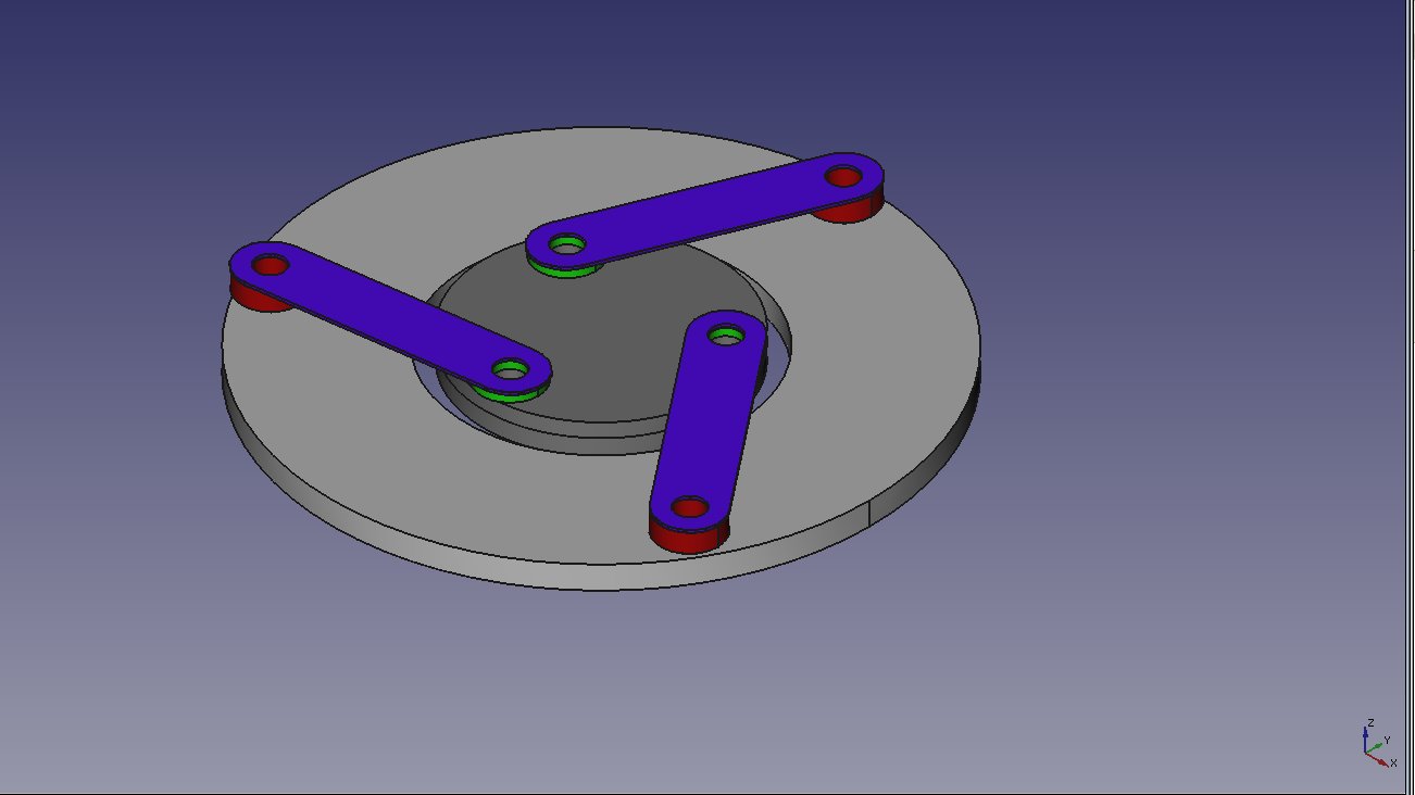
The more I pondered
the situation, the more I thought that modifying the clutch to
operate like the ones on older cars would be the best way to
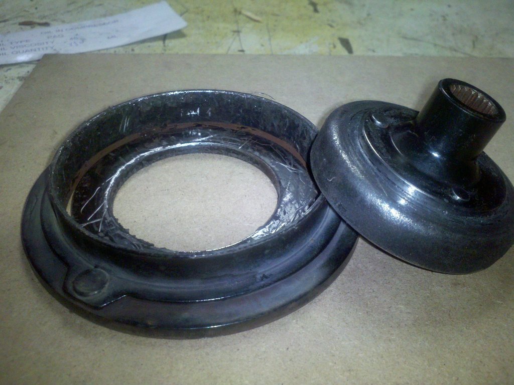
go. The actual design of the clutch would be pretty simple.
There were three rivets in both the hub and the clutch plate
and the design called for three flat springs. Nothing to do
here except to get the old rivets out, remove the parts used
for the rubber ring and install my three springs. Since I have
a small lathe and milling machine, doing the modifications
would be straight forward. The big unknown would be how thick
the springs should be. They would need to be flexible enough
to allow the clutch plate to be pulled into the pulley when
the AC was on and still have enough tension to be able
to return the clutch plate to the disengaged position with the
AC turned off or when it was cycling.
 |
 |
|
|
|
I spent a day working up the design using a couple CAD programs. I ran my ideas past my engineer friend, Scott, who provided some help and some confirmation that what I was attempting was the best plan of action given the circumstances. Some of the design considerations I came up with are as follows.
Considerations:
1. The springs need to point in a direction that allows the
compressor shaft to be pulled, not pushed, by the springs.
2. The minimum air gap between the clutch disk and pulley
needed to remain at the stock distance of about 0.020". I
could use a wider gap if the new springs had less tension than
the original rubber spring.
3. The springs needed to be raised on the center hub enough to
allow them to flex at least 0.020" without having to bend
around the center hub.
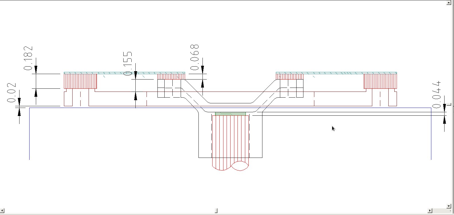
4. The relationship between the height of the center hub and
the clutch plate needed to stay the same as the original
parts. This worked out to 0.155" between the top hub and
clutch plate. (See 2D drawing below.)
5. I would use the 0.044" shim that came under the clutch hub
to try and maintain the 0.020" air gap. I would purchase an
assortment of additional shims in case the air gap needed to
be greater than the original 0.020" gap.
6. I would need to add a disk or washer on
top of the springs to prevent the springs from flexing the
wrong direction with the AC in the off position.
Unknowns:
1. Amount of magnetic force generated by clutch coil.
2. Amount of force necessary to turn AC compressor.
3. The needed thickness/stiffness of the springs.
 |
 |
|
|
|
 |
 |
|
|
|
 |
 |
|
|
|
 |
 |
|
|
|
 |
 |
|
|
|
 |
 |
|
|
|
The nice thing about a clutch using the flat spring design is
that it won't self-destruct if the clutch plate gets hot. All of
the parts on the clutch disk assembly are steel. Unlike the
rubber "spring" on the original clutch, overheating the clutch
plate will not ruin the new steel springs. This clutch should
last for the life of the air conditioning system.
Update: May 2015
The new compressor clutch worked for about 2 months, then broke
two of the clutch springs. I was a bit baffled by this. The
breaks occurred were I had bored the holes to attach the spring
to the outer disk with steel rivets. The breaks appeared to be
from an undue amount of stress at this connection. The steel
rivets had almost been sheared. Very strange. I checked the
compressor and the shaft turned freely, so I assumed that it
hadn't locked up. I made some new springs from thicker stock -
some 0.032" feeler gauges - and we put it back together and sent
my son on his way. Two months later, we had the same situation
again. This time one rivet had sheared and two of the three
springs had broken. My son sent me the clutch through the mail
and I didn't have a chance to check the compressor this time. I
rebuilt the clutch yet again and waited until the next time he'd
be in town to install it.
When he came up, I went to install the clutch again, we found
that the compressor shaft was locked up tight when trying to
rotate it clockwise. I was able to turn it counter clockwise.
When I again tried to turn it clockwise, it now turned. It now
appeared that we had an internal problem in the compressor. The
whole situation was now beginning to make more sense. The
compressor was the cause of the first burned up clutch, as well
as the two subsequent clutches.
Michael ordered a new compressor from http://www.justforjeeps.com/accompressor1.html
and also ordered a new receiver drier in case some metal
shavings got into the lines. We got the compressor and
receiver drier installed last week. I would have liked to have
stripped down the compressor and find out what had happened,
but there was a core charge on the old compressor that he
didn't want to lose out on. So I guess that we'll never know
the reason for the compressor locking up randomly, but I guess
that's life.
To add insult to
injury, the air conditioning clutch coil on my Dodge 2500 died
a few days before we installed his compressor. The coil is
inexpensive as an aftermarket part, but the coil is controlled
by the fuse box which is properly named the Totally Integrated
Power Module (TIPM). The TIPM saw that the coil was drawing
too much amperage and has shut down that circuit. I have the
coil installed, but am presently waiting on some software from
AutoEnginiuity that may allow me to reset the TIPM. If this
proves successful, I may write up the procedure. Always
something to keep me busy.
© Fager November 28,
2014