Repairing a John Deere 317 - 48" Mower Deck
October 16, 2014
We've had a lot of rain
this summer and fall. (I wish we could ship some of it to
Southern California where it's needed.) Anyway, lately it seems
that every time I get ready to mow the lawn, it rains. This had
been going on for a couple weeks and the grass was getting
pretty tall. Finally mother nature strung together two sunny
days in a row and things had dried out enough that I could make
an attempt to mow. I did my routine checks of the little Deere
317 and found that the hydro sight tube was below its usual
level. Being in a hurry, I topped it off and fired the tractor
up. I thought it a bit strange that the hydro fluid was low but
there were only a couple drips on the ground under the tractor
and I remembered that I had spilled some Hy-Gard last year. I'd
check for leaks later. More rain was forecast for later this
afternoon and I had a few acres to mow. I backed the 317 outside
the garage and flipped the PTO switch so I could cut down the
weeds outside the garage door and started to mow. The mower deck
sounded good for a moment, then the pitch of the whirring blades
sounded different. "I know that sound," I thought. "Crap, I've
thrown the deck belt."
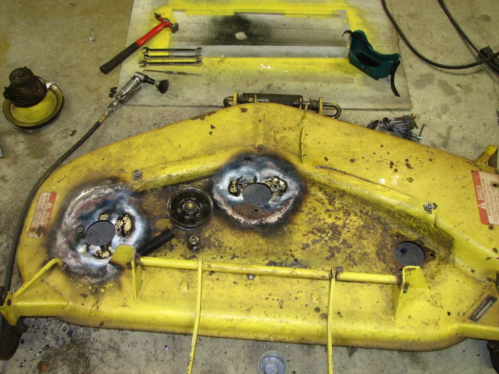
I swung around the
corner and drove straight into the shop. About 10 minutes later,
I had the deck belt covers off. It took me a couple moments to
make sense of what I saw. The center and left side spindle
pulleys were about an inch lower than the one on the right side.
I grabbed the center pulley and pulled. I was able to lift it up
about an inch. Something's not right here.
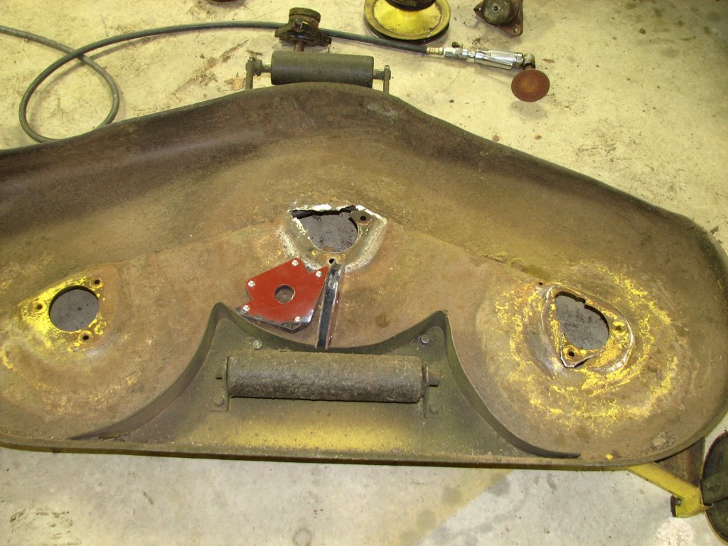
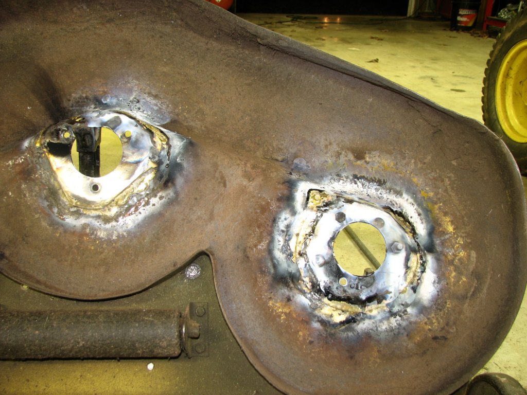
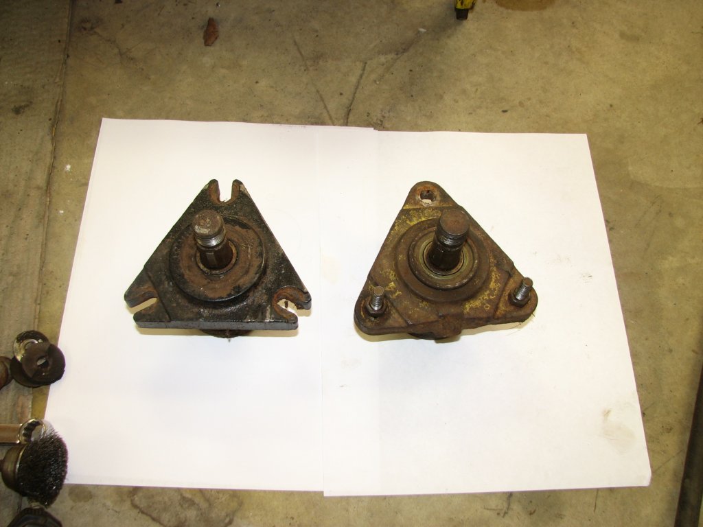
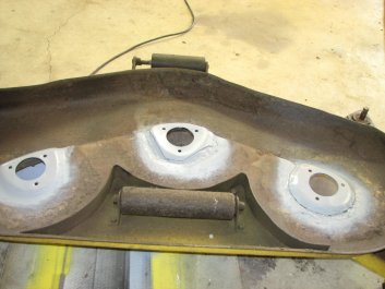
It turned out that the
sheet metal that supports these two spindles had cracked and
broken. The cracks appear to be from metal fatigue. I pulled the
deck off the tractor and removed all three spindles. The area of
sheet metal that supports the two spindles had failed pretty
spectacularly. The third one looked fine. With two spindles
broken free from their mounts, it was no wonder why the belt had
come off.
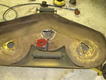
|

|
There's not a whole lot left of the mounts for
the center and left side spindle.
|
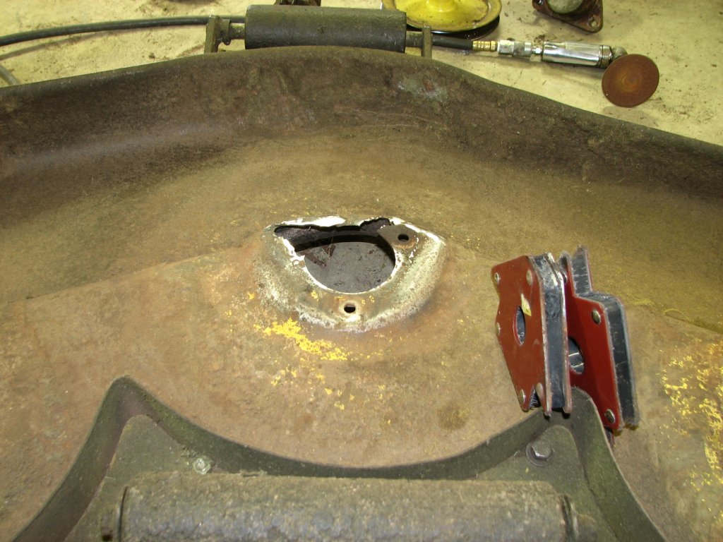
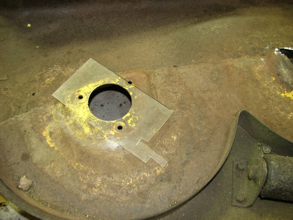
This is what is left of the center mount.
|
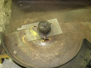
The mower deck on this tractor had seen some abuse prior to
becoming mine. After purchasing the tractor, I had had some
trouble getting the mower to cut level. When I stripped down the
deck and replaced the spindle bearings, I found that the deck was
twisted. Someone had run the deck into something pretty hard. I
had been planning to look for a deck shell or maybe purchase a new
deck this winter. However, I still have grass (and weeds) to mow,
so I was going to need to repair this deck for the time being. I
had some 16 gauge sheet metal left over from another project and
figured that I could make up some patch panels to repair the
damage.
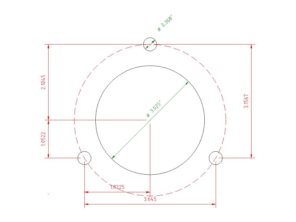
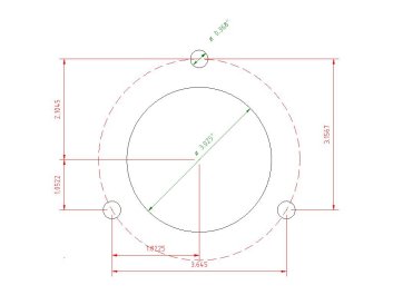
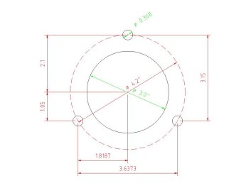
I took some measurements of the not broken right side spindle
mount and drew up a CAD sketch of the hole layout. The bolt holes
were a very close fit on the 3/8"-16 carriage bolts that hold the
spindles to the deck. I measured the holes on my deck to be
0.366". The closest drill bit I had to this was a letter drill
size "U" at 0.368". I measured the center hole at 3.025". I
figured that it had probably been an even three inches when new,
but there had been a lot of rust and corrosion since that time.
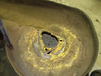
|
|
The left side mount is in pretty bad shape
too.
|
A CAD sketch of the mounting hole layout per
my measurements.
|
I made up a template using a piece of scrap clear plastic and
checked the fit. It was a very good match to the holes in the one
good mount I had left. After I got the patches installed, I
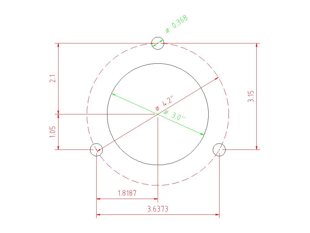
started thinking about the measurements I had taken. The
measurement I had come up with for the three mounting bolts was
2.1045" from the center point. This gave me a bolt circle of
4.209". I figured that on a new deck this bolt circle would
actually be 4.2". I ran my idea past an engineer friend and he
agreed. I drew up another CAD sketch with what I think are the
stock layout for the holes; a 4.2" bolt circle and a 3" center
hole. As I said, I used my first measurements and the patches came
out fitting real nice, but my guess of the proper measurements are
shown in the second sketch.
|

|
A revised sketch which is probably very
close to the mounting holes that Deere used on the
deck.
|
I made a Plexiglas template using the
original measurements I had made. It fit quite
well.
|
I made the first patch just large enough to cover the damaged
areas and give me some area to weld to. I cut a couple "V" shape
notches to make the patch easier to bend over the ledge at the
front side of the center mount. I used a grinder and orbital
sander to clean the metal under the patch as best as I could. I
liberally coated the cleaned metal under the patch and the back
side of the patch with flux and used bolts and clamps to position
the patch on the deck. I was hoping that the brazing rod would get
wicked between the patch and the deck and give it a little more
strength than I could get from brazing around the outline of the
patch alone.
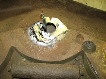
Once I had one side of the patch secured, I heated a section of
the patch and formed it to match the deck with some auto body
hammers. I then brazed the newly bent section to secure it. I
continued this process as I worked my way around the patch. I had
considered securing the patch by cutting out the deck to match the
patch panel and using butt welds. It would probably have looked
nicer, but wouldn't have been as strong. I will have two layers of
metal for much of the mount. It also would have been more
work to match the raised area around the mount. Considering the
condition of the deck, my goal was to get it useable again. If I
can achieve that, I will be happy.
|
|
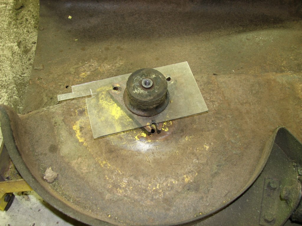
The template matched up with the spindle
housing as well. Time to cut some sheet metal.
|
The sheet metal has been cut and I am starting
to braze and hammer form it to fit the spindle
tower.
|
Once I got the first patch finished, I started thinking about the
second patch. This side of the deck had a lot of hair-line cracks
radiating out from the mounting area. The patch was going to need
to be a little larger. Again, the bolt hole area was missing for
one of the bolts and where the other two holes were, there wasn't
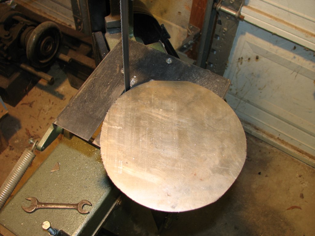
much metal that wasn't cracked. I decided to cut this patch in the
shape of a circle with a small flat area to fit down into the side with the ledge. To cut the circle, I
added the little table to my 4" X 8" horizontal band saw that
allows it to cut in the vertical position. I don't use this table
too often, but it sure came in handy for this project.
|

|
The opposite view of the previous picture. The
notches make it easier to bend the patch to fit the
spindle tower.
|
For the left patch, I started with a circle
with one flat side. The flat will get bent down to
align with the ledge to the front of the raised
spindle mount.
|
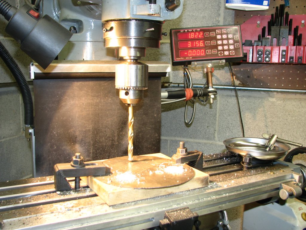
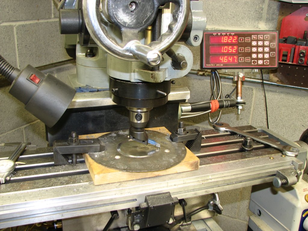
I made the circle seven inches in diameter
and set it up on a piece of pine board backing on my milling
machine. I marked the center of the disk and drilled the size
"U" bolt holes. I had looked up the size of a clearance hole for
a 3/8" bolt and found that size "W" is often used. Size "W" is
0.386". I had measured 0.366" on the rusty holes on the right
side of the deck. As my friend mentioned, it appears that the
design considerations were to minimize any play in the spindle
housing to deck junction if the bolts were to loosen. With the
size "U" bolt holes, the bolts are a very snug fit.
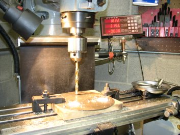
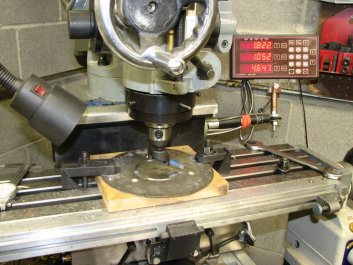
Next I turned my attention to cutting the 3.025" hole for the
center of the spindle housing. Since I don't have an offset
boring head, I made do with a fly cutter with an angled bit. The
fly cutter works well, but setting the bit to cut a precise hole
involves some trial and error. It took a few test cuts on some
scrap before I was able to cut the hole diameter I needed. Once
the bit was set correctly, cutting the center hole went quickly.
|
|
Drilling the letter size "U" (0.368") holes in
the patch.
|
Here I am using a fly cutter to cut the hole
for the spindle housing.
|
With the second patch made, it was back to brazing. I used the
same method as before and tacked one side, then heated and bent
the sheet metal to the proper shape. Again I used a lot of flux
between the patch and deck and fed brazing rod into the weld until
I saw that the bronze had been wicked between the parts. Once I
finished brazing the bottom side of the deck, I turned it over and
started on the top side. I clamped the broken fragments into their
respective positions and brazed them in place. Since the spindle
housings sit on the top side of the deck, my goal was to build up
the top side so that the two cracked mounts were at the same
height as the undamaged one. I have always had a belt alignment
problem with this deck due to the metal under the spindle housings
being bent and sagging a bit. Now I had a chance to improve the
alignment by making sure that the height of the deck was uniform.
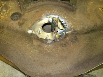
There were lots of little pieces of broken sheet metal to clean
and braze into position. After I took the picture below of the
deck top side, I spent another couple of hours brazing, grinding,
and leveling the two mounting areas.

|

|
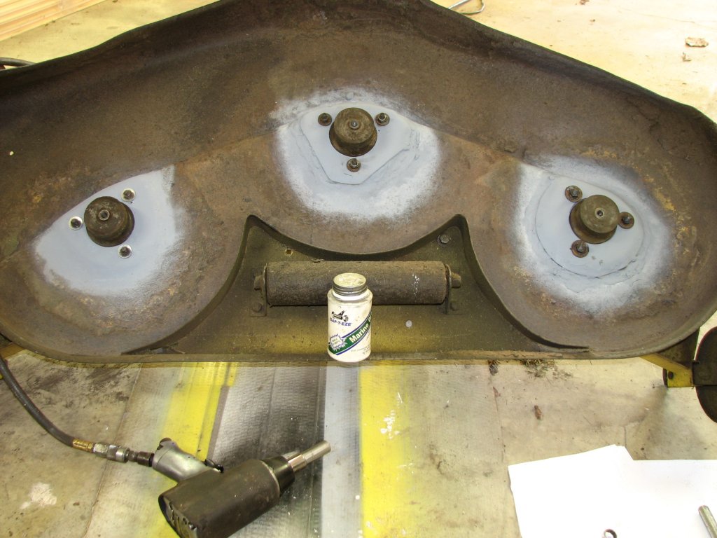
Both patch panels have been brazed in place.
|
On the top side of the deck, I brazed in all
the broken pieces. I did this so that the height of
the spindle housing would be the same as the not
broken right side.
|
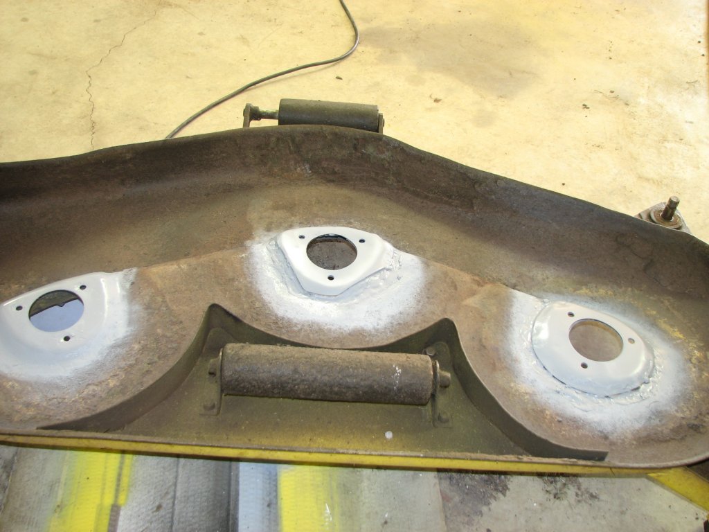
When I finished brazing, both sides of the mounting areas were
ground and sanded flat and painted with a couple coats of primer.
If my repairs hold up, I will strip the deck down this winter and
get a few more coats of paint on it to try and keep the rust at
bay until I can find a nice deck shell to replace this one. A
wider deck would be ideal but they're even less common than the 46
and 48 inch decks, but who knows, I may get lucky.
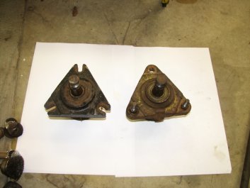
When I was talking to my friend about the size of the bolt circle,
he mentioned measuring the spindle housing as another reference in
addition to measuring the holes in the deck. I have two different
styles of housings. One with slots instead of bolt holes and one
with square holes to capture the carriage bolts that Deere uses to
hold the spindle housings to the deck. After measuring the housing
with the square holes, I am pretty confident that the bolt circle
is 4.2".
|
|
Primed and ready for the spindle installation.
|
Comparing the two different styles of spindle
housings.
|
The last time I had the spindle housings out of the deck was
November 2010 when I replaced the spindle bearings and added power steering
to the 317. Four years later, all nine of the spindle housing nuts
and bolts came apart easily. The main reason for this was that I
used an anti-seize compound on all of the threads. I had never
used anti-seize on anything but spark plugs in aluminum cylinder
heads until we moved from California to Virginia in 1986. The
mechanics in the Maryland dealership I worked for used it for all
nuts and bolts that were exposed to weather and swore by it. With
road salt being used for winter snows and lots of rain the rest of
the year, there was a need for using it. In California we didn't
have much of a rust and corrosion problem. I started using it for
my projects at home and now wouldn't be without it. Last year, I
found a anti-seize product for use in marine environments. I
haven't been using it for long enough to know how it holds up
after a few years, but everything I have used it on has come apart
easily. I am hoping that it does an even better job than the
non-marine stuff I have been using for decades.
I lubed up all of the nuts and bolts and installed the spindle
housings. I sharpened the three blades and installed them. The
blades are getting pretty rounded on the ends. I think it's about
time to buy some new ones. I installed the belt and was real happy
that the idler pulley alignment with the center blade pulley was
better than it's ever been. This should make my belt last a little
longer. The deck was now ready to be installed back on the
tractor. However, there was one last thing to check.

|

|
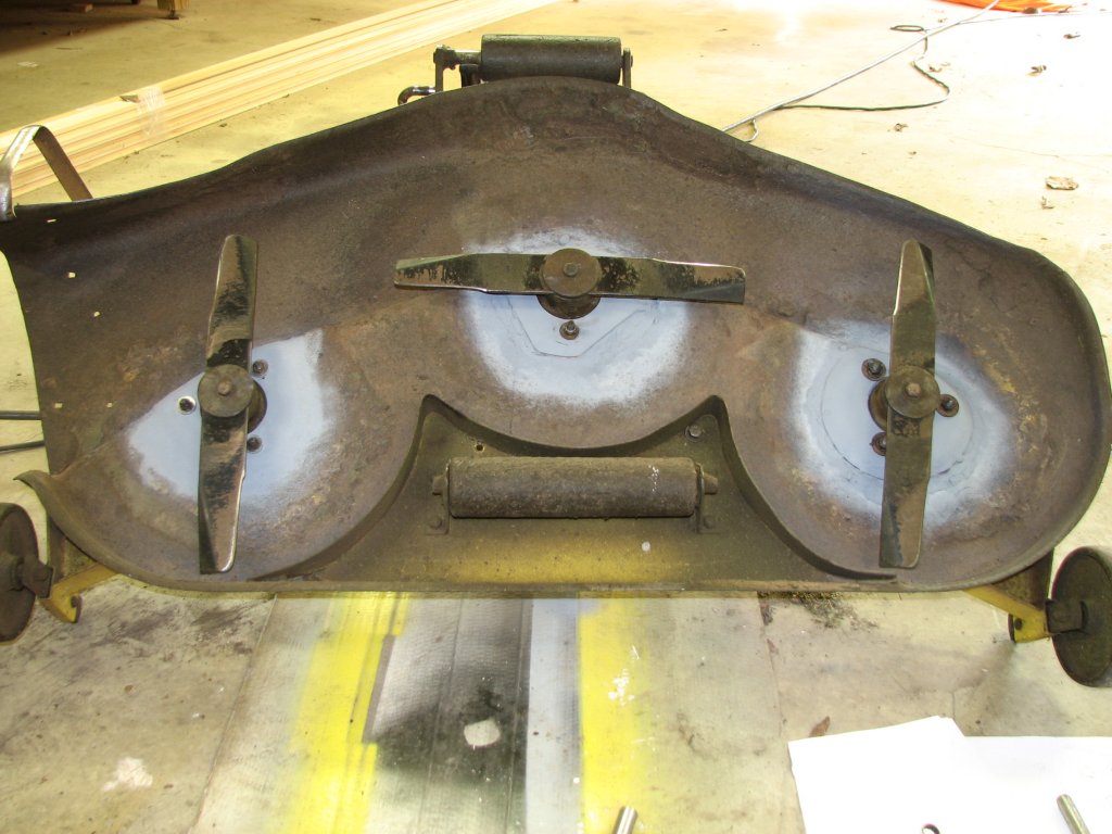
The spindles are installed.
|
The blades have been sharpened and installed.
(I really could use some new blades.)
|
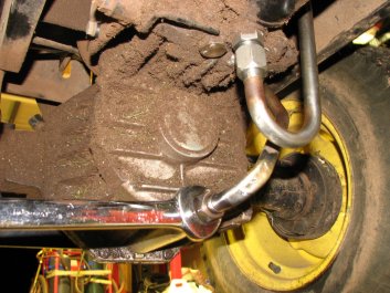
Last Tuesday when I thought I was going to mow, I had checked all
of the fluids before starting the tractor. While this is my usual
practice, finding the hydro fluid a little low in the sight tube
was not a usual occurrence. I topped of the level with Hy-Gard low
viscosity fluid and checked under the tractor for leaks. There
were a couple fresh drips on the ground and the bottom of the
transmission had some oily dirt on it, but it didn't appear to be
a big leak. I figured that I would pressure wash the tractor and
find the leak after I mowed. As it turns out, it is a good thing
that the mower deck had trouble and that I couldn't mow. The leak
only happened when the hydro was under power and it was a pretty
good sized leak.
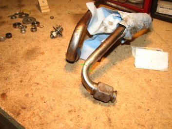
I was pretty certain that I could silver solder the crack and
close it up, but the question was how long it would stay sealed.
The tube is attached to the bottom of the transmission and extends
upward to form a loop. When the tractor is running, the loop
vibrates and there is no upper mount to dampen the vibration. I
didn't think that my silver solder would hold forever, but I was
hoping that it would hold long enough to get the yard mowed before
our party on Sunday.

|
|
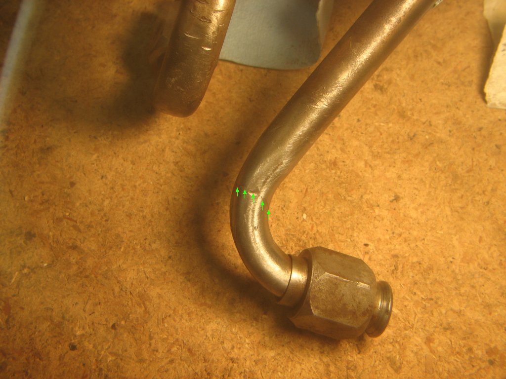
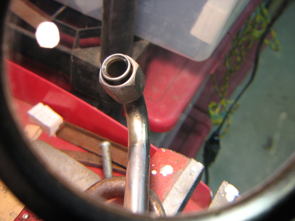
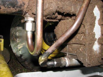
I found out where the Hy-Gard was going. A
hair-line crack 2/3 the way around the cooler pipe.
|
It was hard to see the crack in person. It was
harder to get it to show in a picture.
|
I started mowing around noon. It usually takes about four and a
half hours to get all of the lawns and the trails done. The deck
was working well aside from leaving a thin stripe of long grass
where the rounded ends of the blades didn't cut. I stopped every
15 minutes or so to check the cooler pipe for signs of leaks. No
leaks for almost two hours. I finished up on the back yard and
started mowing in front of the house. After a few minutes of
mowing, I decided to check the cooler tube again. This time there
was a drip hanging off the pipe. I'd better get the tractor back
to the shop. After I covered the 50 yards back to the shop, the
drip had turned into a tiny stream. I had caught the crack early
enough that I didn't lose more than a couple ounces of fluid.

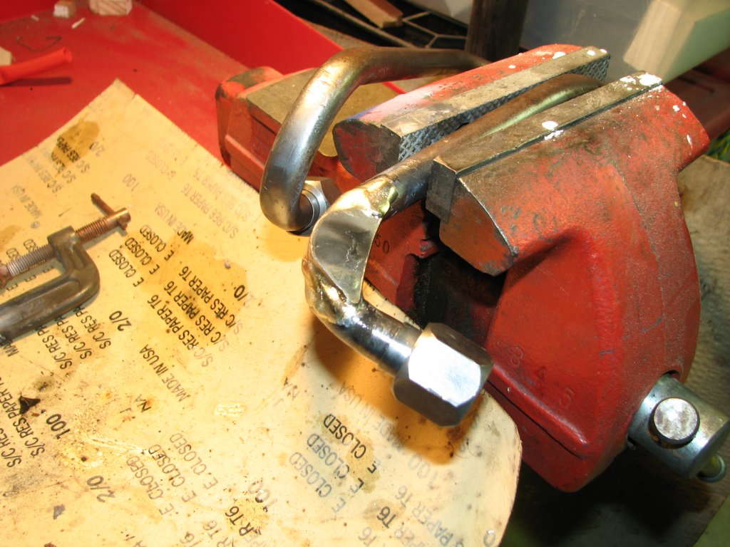
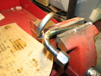
|

|
Low
heat
from the Oxy-Acetylene torch, lots of flux and
some silver solder sealed up the crack, but will
it hold up?
|
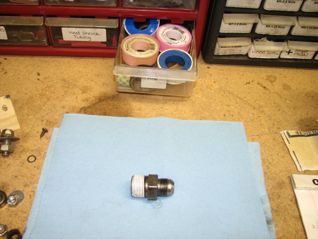
I removed the adapter, cleaned the threads and
added some Teflon tape to help prevent future leaks.
|
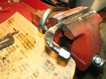
I drained the Hy-Gard and pulled off the cooler pipe again. I
would order a new pipe on Saturday. I still wanted to get the lawn
mowed, so I decided to try brazing the pipe. I used a grinder and
a small disk sander to remove as much of the silver solder as I
could from around the crack. I coated the pipe in flux and heated
the pipe just enough for the brazing rod to flow and follow
gravity downward. With the crack facing down I added enough rod
that some drips started to form on the bottom of the pipe. I
was trying to get as thick of a coating over the crack as I could.

|
|
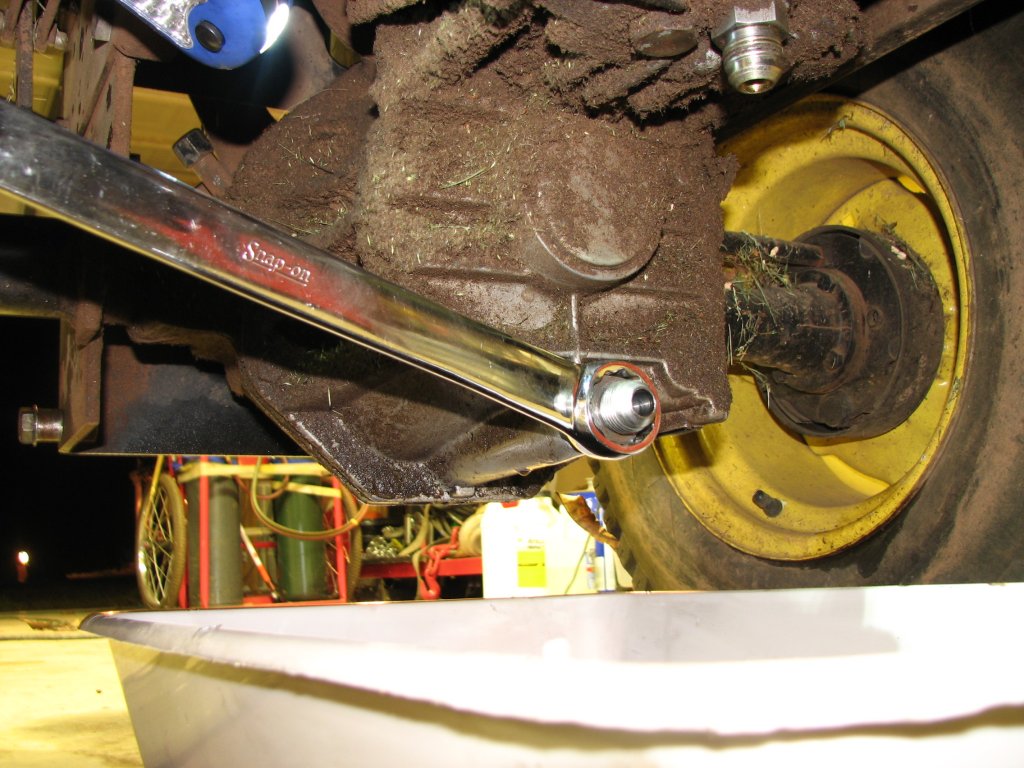
Using a 1-1/8" wrench to tighten up the
adapter.
|
A 1" wrench is used to tighten up the cooler
pipe fittings.
|
After the pipe had cooled a bit, I plugged one end and pressurized
the pipe using a rubber tipped air chuck. I dipped the pipe in
some water to look for bubbles. No bubbles were found, so
hopefully that means no leaks. I had been thinking that I wished
that there was some way I could secure the pipe so it didn't
vibrate quite so much. There may well be a way to secure the upper
looped end of the pipe, but that would mean pulling the fender pan
off the tractor to get a good look at the possibilities. That
would take some time and I didn't have a lot of time to spend on
the tractor right now. I decided that I could add a gusset
to the bend where the crack had formed and this might be enough to
buy me a few hours of mowing time.

|
|
Back
to the drawing board. This time I will braze
with a bronze alloy and hope for the best.
|
I let the braze drip a bit and made sure that
gravity guided the drips on top of the crack
|
I cut a small triangular piece of sheet metal and ground it to the
approximate shape of the bend. I covered the side that would be
facing the pipe with flux and tinned that side with braze. I did
the same to the area of the pipe that the gusset would attach to.
With low heat, I then brazed the gusset to the pipe. I
reattached the cooler pipe to the transmission and ran the Hy-Gard
that I had drained through some paper filters to make sure that I
hadn't picked up any dirt. I had used the last of my jug of
fresh Hy-Gard when I had filled the transmission on my first
attempt to seal the leak. Now all I had was what I had drained
before removing the pipe for the second time. I wasn't going to
have enough to fill the trans to the proper level and I wasn't
going to mow being low on fluid. I would hit the Deere dealer
tomorrow and get another gallon of Hy-Gard low viscosity when I
ordered the new cooler pipe.
|
|
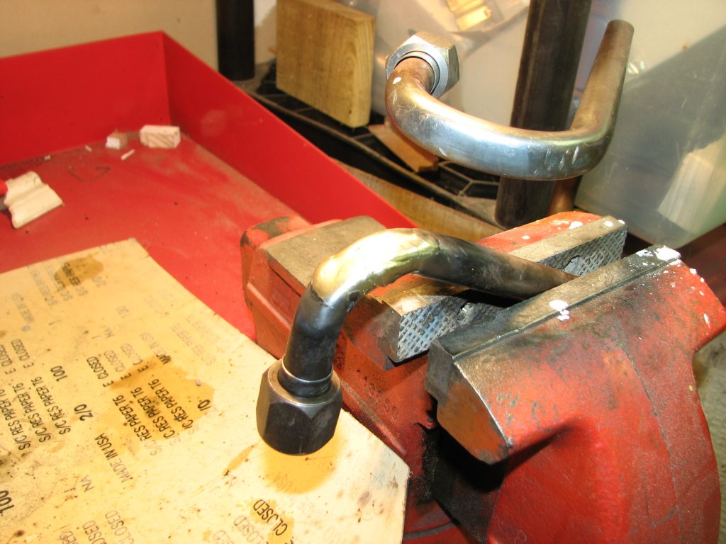
To
reduce the amount of movement at the point where
the tube cracked, I brazed in a gusset.
|
Once again, I installed the cooler tube. It's
a little too dark to try it tonight but I am hoping
to be able to finish mowing the lawn tomorrow.
|
Saturday morning we took a ride up to the Deere dealer. I bought a
new belt for the deck, some Hy-Gard, and ordered the cooler pipe.
The parts counter guy said that the pipe should be in on Wednesday
with their stock order. I had no desire to pay extra to get the
part sooner. If I couldn't get the yard finished today, I didn't
really care if I mowed on Monday or even next Friday.
It took about a half hour to install the new belt and fill the
hydro. Time to see if it works. Again, I stopped to check for
leaks often. I found none. I got the front yard finished and
started on the trails. I was a little hesitant about mowing the
trails. There are lots of pot holes, tree roots, and rocks to
contend with. I would also be a good distance from the shop
if I developed a leak. However, the grand kids enjoy walking down
to the creek and the weeds were getting pretty tall. I took a
chance and mowed the trails. Fortunately the pipe held and even
hitting the big ruts didn't cause the crack to open up again.
After I get the new pipe installed, I will keep this old one as a
spare. As long as I keep it around, the chances are that I will
never need it.
© Fager October 18, 2014