Repairing a John Deere 301 Industrial Tractor
April 18, 2013
Even before we bought the home in the country, I've been wanting a tractor a bit larger than my little Deere 317 garden tractor. At the old house, I didn't have enough property to warrant a larger tractor, but I still wanted one. :) If the truth be told, I just like machines. Now that we have the new home with some acreage, I have more reason for a larger tractor. There is a fair amount of brush and soil removal that needs to be done and a tractor with a loader would make that job a bit easier. However, with all of the remodeling we're doing, I couldn't justify spending a lot of money on something that would get limited use. That said, I figured that if I was patient, something would come my way in my price range. After a year of looking, it finally did.
|
|
|
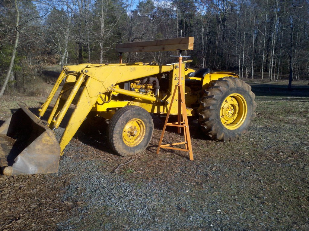
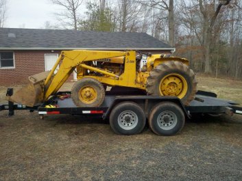
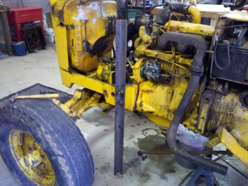
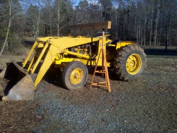
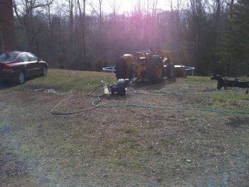
Tractor comes home. Not a bad drive with the tilt trailer - though I had the tractor a bit too far forward on the trailer.
|
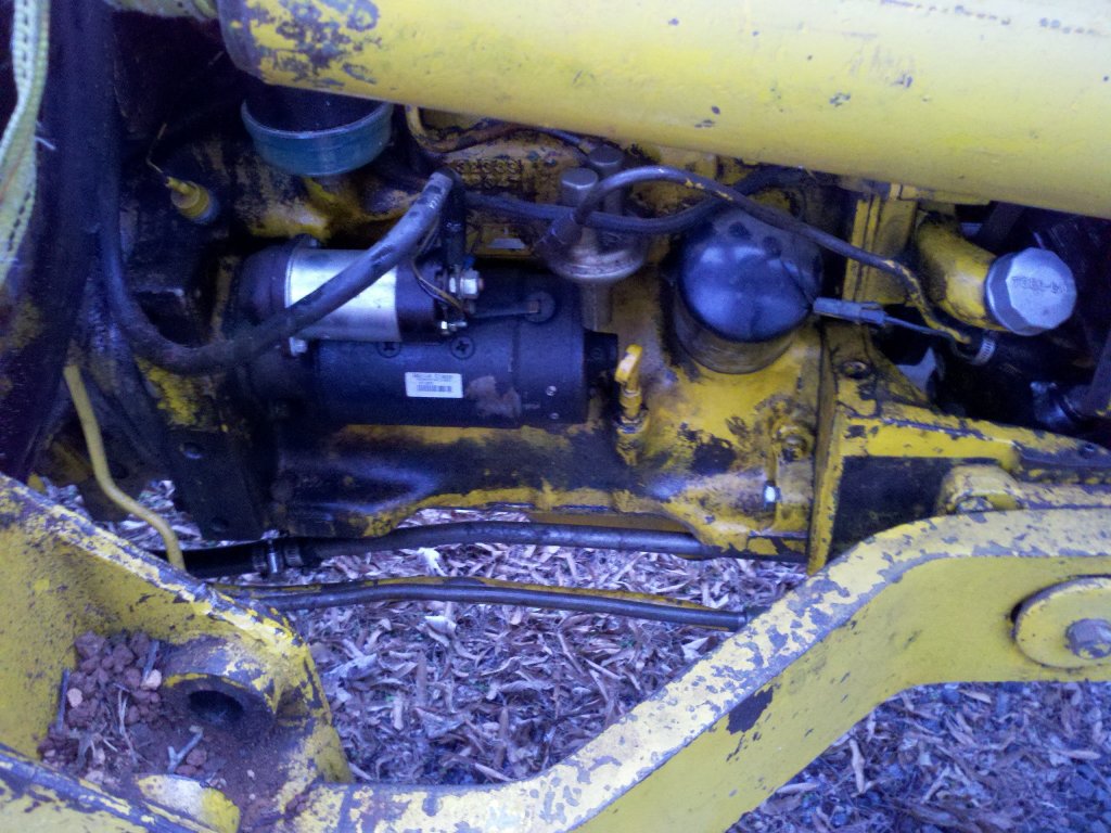
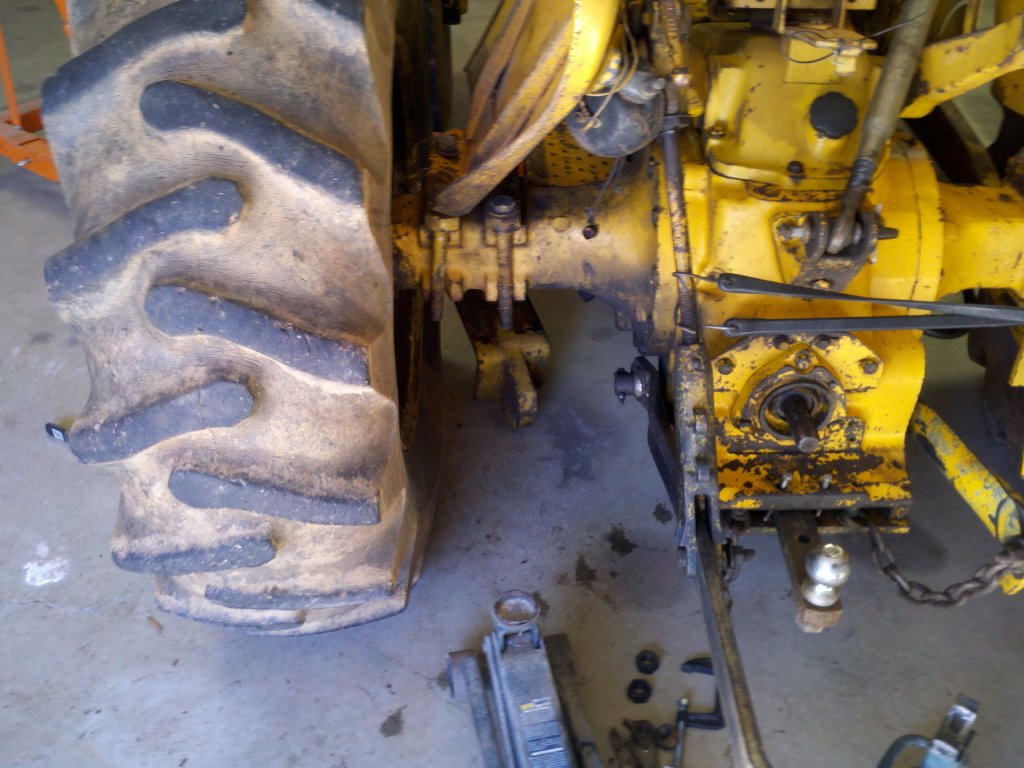
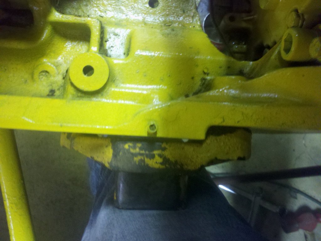
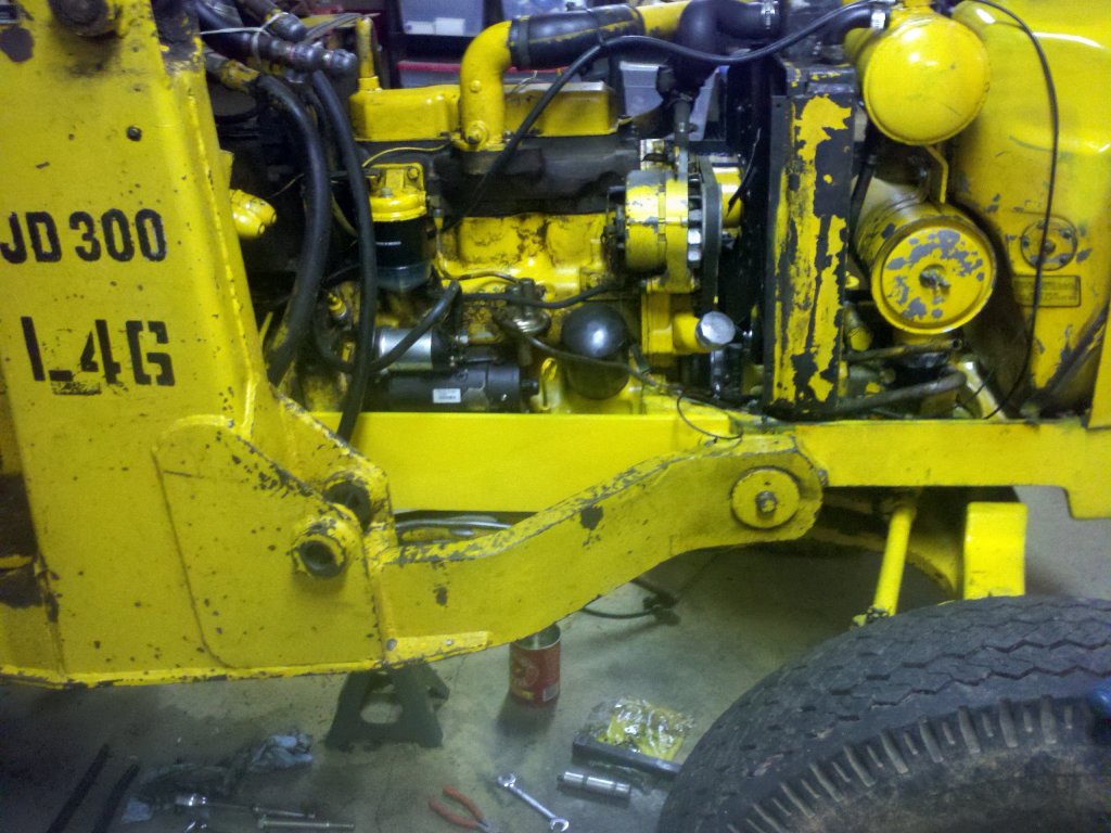
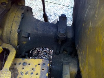
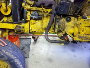
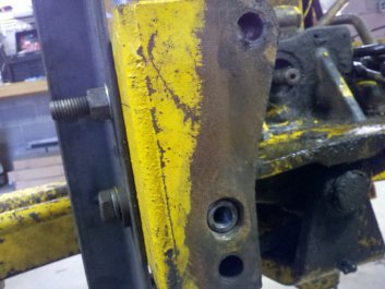
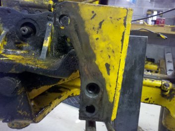
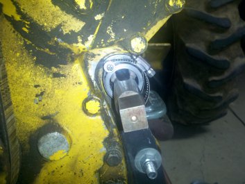
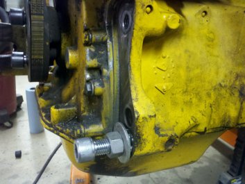
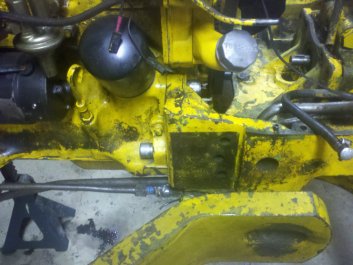
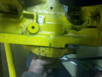
Temporarily holding sub-frame to engine block. You can see the space where the front end is coming loose to the left of the shiny bolt.
|
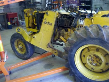
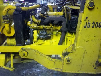
The "new to me" tractor is a 1972 John Deere 301 industrial tractor with a 300 (7320) loader. I didn't pay a lot for it as there were a couple issues with it. The biggest issue is that the six bolts that hold the front sub-frame, which in turn holds the front axle, have pulled out. Not once, but twice. The previous owner had tried to fix the stripped threads the first time. After they pulled out again, he took the tractor into the Deere dealer. The dealer put six new thread inserts in and buttoned it back up. The new inserts failed within six months. The owner gave up and it's my problem now. Yes, I am a glutton for punishment.

|
|
|
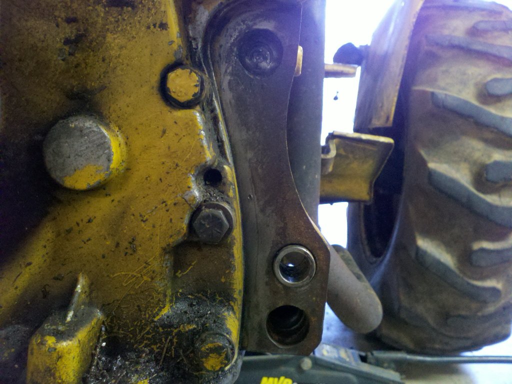
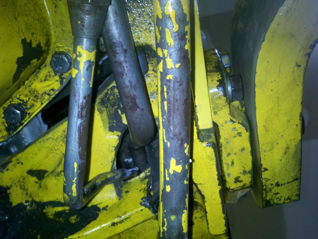
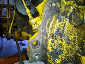
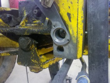
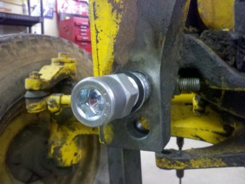
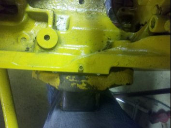
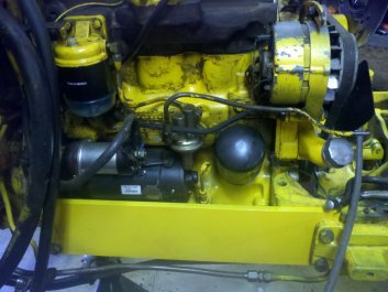
Right side of block and sub-frame.You can see a dark area to the right of the silver bolt - a square - that makes it look like something was bolted there and is now missing.
|
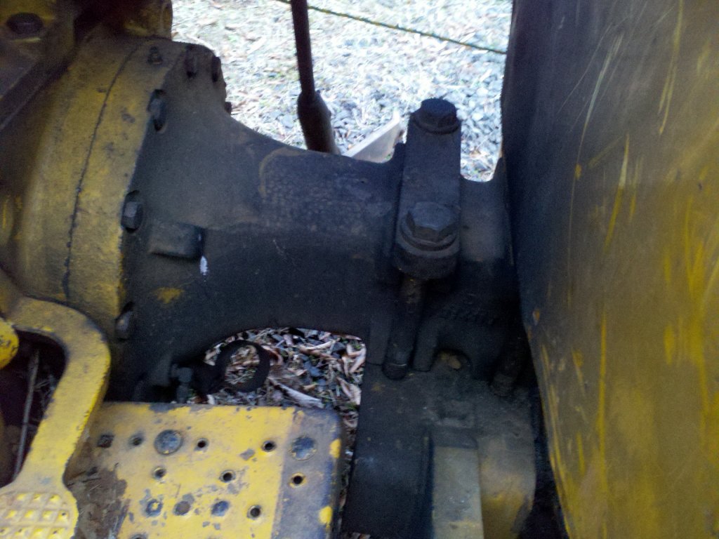
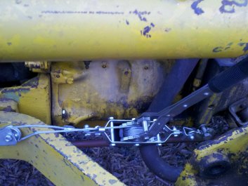
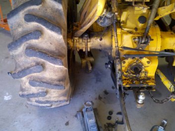
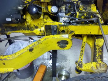
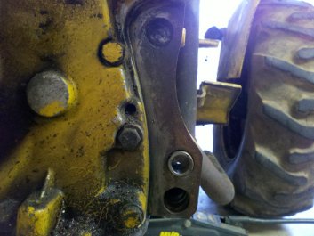
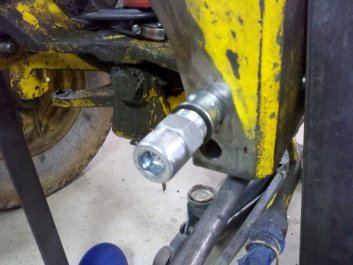
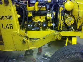
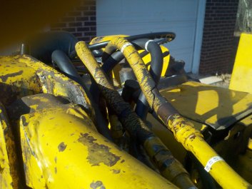
Four bolts on each side hold loader frame to rear end. Two are visible and two are behind the fender to the right. These bolts were all loose.
|
My task is to replace the threaded inserts - once again - and make sure that this time it stays fixed. I figured that I had one shot to fix this issue without having to replace the engine block, so I'd better think about this long and hard before I began work.
I started researching the problem. There wasn't a whole lot on the tractor sites about this problem. However I did notice while looking through the Deere parts manuals online that there appeared to be a couple of side supports (braces) that were used when a certain model of loader was installed and they were not on my tractor. These supports run from the flywheel housing, at the rear of the engine block, forward to the sub-frame that had come loose. The part numbers were T21653 & T21654. I found one post that mentioned them and a little more digging led me to believe that these side plates were supposed to be installed when certain loaders were used. My question was "which loaders". At this point, I didn't know. The side supports looked like they would lessen the stress on the sub-frame to engine block junction where the bolts had pulled out of the threads. From what the previous owner told me, I believed that the front loader was the standard loader for this tractor. He was mistaken.
|
|
|
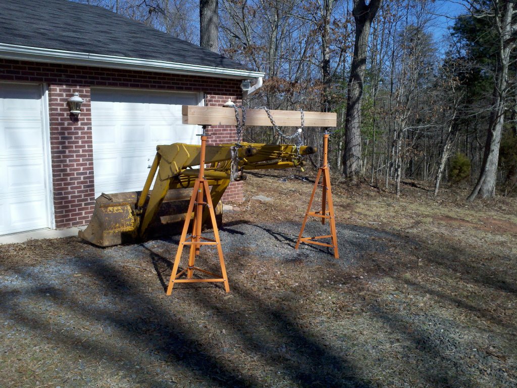
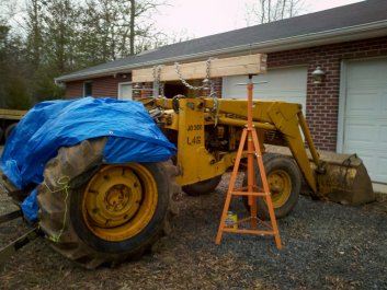
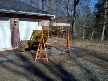
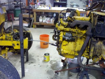
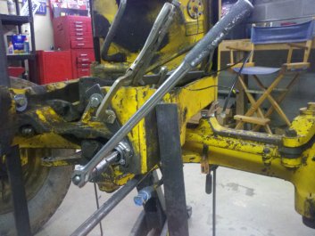
Improvised support to hold loader.
|
The bucket and arms are removed.
|
To get started with the repair, I first needed to figure a way to remove the loader bucket and arms from the tractor and support them while the tractor was being worked on. A gantry crane would be my first choice, but I didn't have one. I ended up making something similar with a couple of Harbor Freight under car stands and some 4x4 lumber. This task was made a bit tougher as one of the stands didn't come with the bolts to assemble it and after calling the HF customer service folks, they couldn't supply them to me. Since I didn't want to make the 65 mile round trip again to return the stand for one with all its parts, I bought new bolts locally for less than the price of fuel to get to my closest HF store. You can bet that I will open the boxes and check for parts on any further purchases from HF.
To keep the 4x4 lumber from falling off the stands, I drilled and tapped some 5/8" threads in the top supports of the stands and inserted a couple pieces of all-thread rod. I drilled holes in the 4x4s to match the two new spikes on the top of the stands and assembled my make-shift gantry. It worked like a champ.
With the loader off and the hydraulic lines sealed with 1/2" pipe caps and plugs, I power washed and moved the tractor into the workshop. I am really happy that I now have a shop that is large enough for this type of work. It sure beats working outside in the cold.
|
|
|
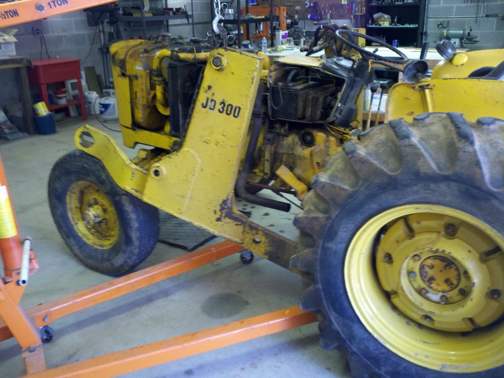
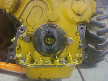
Tractor minus bucket and support arms.
|
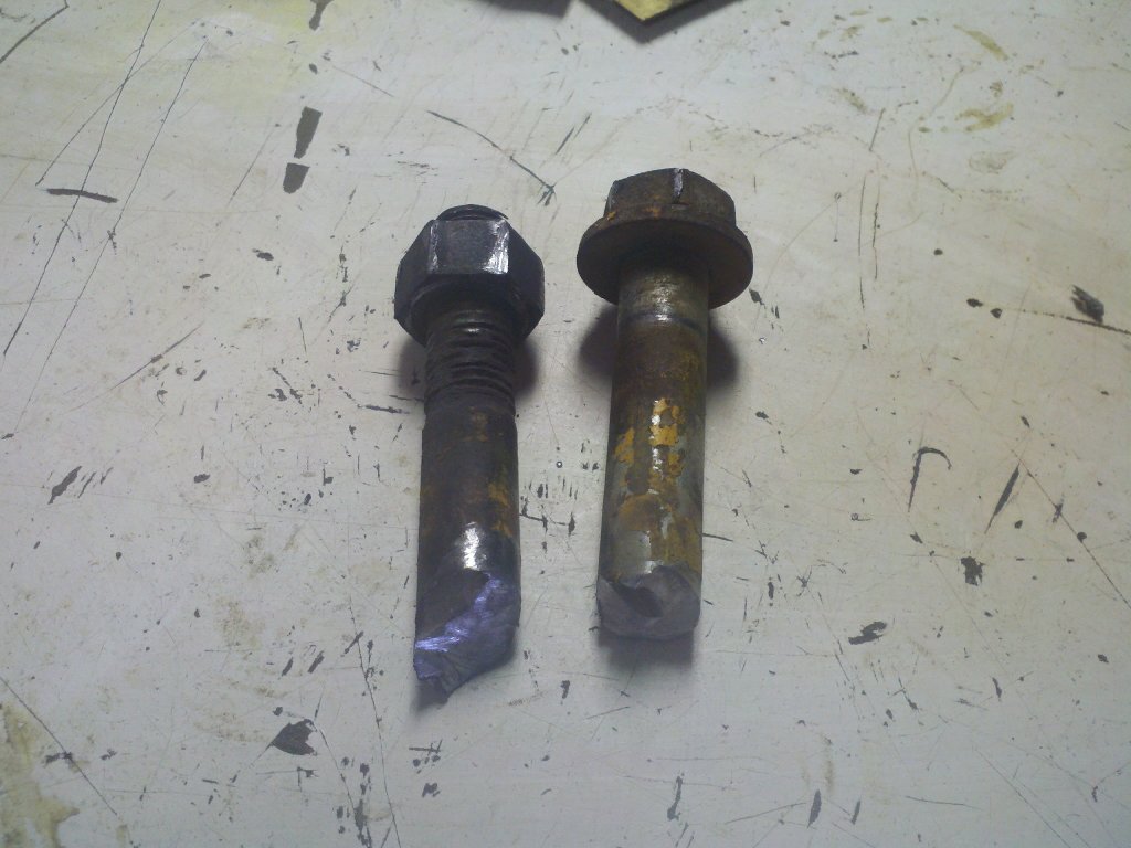
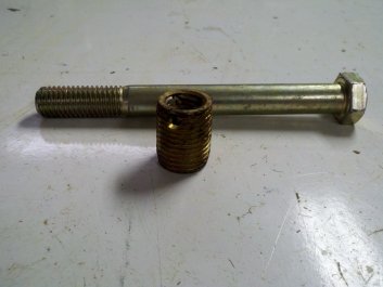
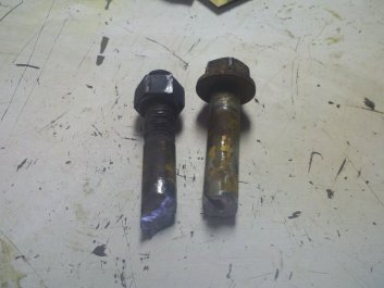
Shot of one of the dealer installed thread inserts that came out. The bolt shown is wrong. Actual bolt is 3.5" long, not 6".
|
I purchased a workshop manual from Deere and read the sections on splitting the front end from the tractor. There were a couple special tools needed to support the sub-frame, but I guessed that I could figure something out to get around not having the Deere shop tools.
Splitting the tractor was pretty straight forward. Pull off some hydraulic lines, pull the radiator and oil cooler, disconnect the hydraulic pump. I jacked the rear half of the tractor up and supported it on jack stands. I cut and drilled a couple pieces of heavy angle iron, then bolted them on to the sub-frame to the rear of the front wheels. I removed the stripped bolts and as I started to separate the tractor, I found that the front section was very unstable. I stopped the split and added a couple of braces in front of the front wheels. Now I could wheel the whole front section away from the tractor.
|
|
|
Left loader frame ready to come off.
|
Loader frame attaches to rear axle - 4 big bolts.
|
My first look at the stripped inserts was disheartening. There were four 5/8" and two 9/16" bolts that held the sub-frame to the block. Four bolts were threaded into the block and two to the sub-frame. Instead of drilling and tapping for helicoils, they had used much larger thread inserts. I'm not sure why this was necessary. It could be that the owner's repair buggered up the holes to the point that helicoils weren't an option. Whatever the reason, where the inserts had pulled out, there were now holes with a diameter of about 0.920". The large size of the holes didn't give me a lot of room to re-drill and re-thread larger. I got out my Machinery's Manual and started looking at thread sizes and the diameter of holes needed for each thread. I read up on whether to tap fine or coarse threads in cast iron. Coarse threads seemed to be the best choice. I knew that I wanted the new inserts to fit the threaded holes tightly and be as strong as possible, so I decided to go with grade eight bolts, 1-1/8" - 7 threads per inch (tpi) as the thread inserts and use a 31/32" drill bit for the holes. The 31/32" drill bit size is 1/64" smaller than the standard bit used for a 75% thread engagement. It gave 84% thread engagement. It was also not that much larger, at 0.96875", than the 0.920" holes. I hoped that making the thread inserts from grade 8 bolts and using a thread locking compound would hold the new inserts in place. I was also hoping that the new side braces I would be adding would lessen the strain on the engine block to sub-frame bolts so they wouldn't pull out again.
|
|
|
Click to enlarge. Blue arrows show bolt locations. Red arrow shows where sub-frame has come loose from the engine block. Green rectangle shows proposed brace (both sides of tractor).
|
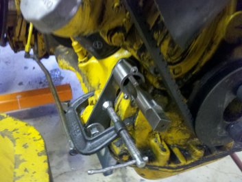
Supports at the rear of the sub-frame. These didn't stabilize the sub-frame enough and I had to add a couple more supports in front of the wheels.
|
I posted an outline of my proposed fix on my local metalworking group and asked for some help. I got some good suggestions. One of the suggestions was to reinforce my proposed side braces with some dowel pins. The Deere parts picture shows that the braces are installed with only four bolts. Two on the front and two to the rear of the braces. I agreed with the idea that if I added some dowel pins, it would take some of the load off of the side brace bolts. At this point, I was still unsure of the forces that the loader would place on the bolts that had pulled out.
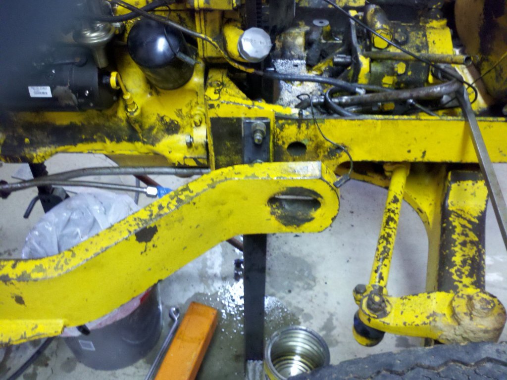
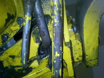
I must admit that this is my first full sized tractor. I am not as familiar with tractor design as I could be. I don't quite understand the design of the loader frame on this tractor. The frame for the loader is a pair of 2+ inch thick steel beams that are bolted to the rear axle of the tractor. They run forward to mounts on the sub-frame that pulled loose. This front mount is not solidly attached. It is nothing more than a thick 3" x 1.5" tab that goes through an oval hole on the front-most end of the loader frame. There is about 0.15" clearance between the tab and the hole. No solid mount up front? Curious!
I drew up a diagram of the tractor and loader and tried to analyze the forces involved when the loader bucket is full. Right or wrong, I have come to the conclusion that the design is meant to transfer the weight of the full bucket to the rear axle through the loader frame. The weight in the bucket tries to lift the rear of the tractor through the long lever that is the loader frame. The lifting force on the rear is then spread out through the rear axle to the transmission, then to the engine and finally the front sub-frame and front wheels. For those not familiar with tractors, many (mine included) have no frame to hold the engine and transmission. The engine and transmission ARE the frame.
So, why is there no solid front loader frame mount? My best guess is that the loader frame acts like a long straight spring and flexes slightly under load. The front tabs are only there to limit the amount of distance that the loader frame (straight spring) can flex. The flexing of the loader frame lessens the shock and momentary high load if you have a full bucket and hit a bump.
|
|
|
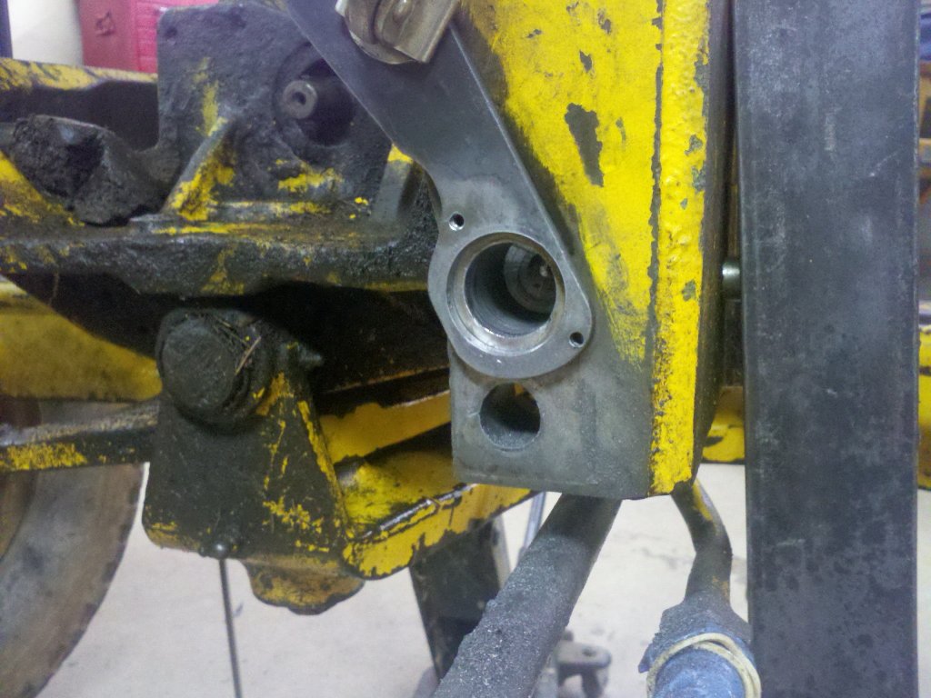
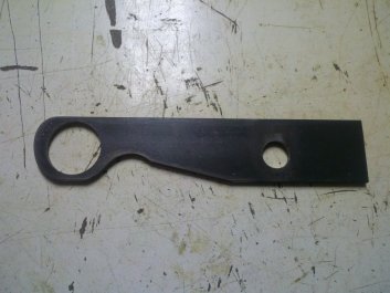
Right loader frame showing the slot that fits to the tab on the sub-frame. The tab piece had already been removed.
|
Sub-frame has been disconnected and moved forward enough to inspect the pulled out threads.
|
When I was removing the loader frames, I found that the eight 7/8" diameter bolts that hold the loader frame to the rear axle were loose. One bolt was loose AND rusted stuck. This told me that it had been loose for quite a while. With the loose bolts, the loader frame was no longer acting like a spring. With the bucket loaded, the loader frame was resting on the front tab attached to the sub-frame. If the tractor went over a bump with a heavy bucket, the loader frame could move enough to slam up and down on the tab. I guessed that this added more load to the six bolts that had pulled their threads out. Between the loose bolts and the lack of side braces, it was a disaster waiting to happen. I was now a bit more confident that if I could do a decent job of installing new threads, I could fix this tractor. We shall see...
Even though a couple of the thread inserts had not pulled out, I now decided to replace them anyway. I just wasn't confident that they wouldn't pull out at a later date. They've had so much stress on them that I couldn't be sure that they weren't damaged. It would be a few hours of extra work, but with new threads, inserts, and larger bolts installed, I would have a bit more confidence in the job.
I worked up a parts list. I'd need a couple 1-1/8"-7 tpi taps. One taper tap and one bottoming tap. The taper tap gets the threads started and the bottoming one allows me to thread almost to the bottom of a blind hole. I'd also need an assortment of large drill bits necked down for my 1/2" chuck hand held drill and (of course) the grade 8 bolts I'd use to make the thread inserts. I had decided to replace the 5/8" and 9/16" bolts with 3/4" bolts. There was just enough room to do this if I chose socket head cap screws rather than hex head bolts. Not exactly stock, but they'd be stronger.
A note here about taps. I try to use only quality - usually American made - high speed steel (HSS) taps. Don't waste your cash on cheap import taps. A broken tap can be a real pain to extract. Tapping into cast iron isn't too difficult with a one and one eighth inch tap so I don't stand much of a chance of breaking it. However, tapping the 3/4" - 10 tpi threads in an undersized hole (80 plus percent engagement) in a grade 8 bolt will be a different story. I chose a new old stock Putnam brand tap from Ebay for this chore. Not a cheap purchase, but quality tools are worth the cost.
|
|
|
Left side of sub-frame. Insert in the center is a little beat up. It will be replaced.
|
Right side of sub-frame. Insert is tight, but it too will be drilled out and replaced.
|
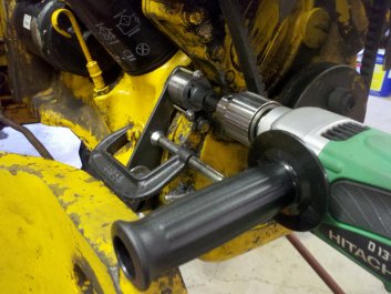
I needed a way to locate and stabilize the drill bit when drilling out the holes to 31/32" and keep the holes straight. I played with some ideas to assemble a makeshift horizontal boring machine out of a couple drill presses, but I found that I couldn't easily center the bits on the holes. I just couldn't get a fine enough adjustment out of my make-shift rig. In the end, I decided to make some drill bushings and a holder to bolt to the flange and center the drill bits. I turned a couple pieces of steel on the lathe and bored them to match the 31/32" drill bit. I made another bushing for the 1-1/8" tap. I made a few more bushings so I could incrementally drill out the two thread inserts that hadn't yet pulled out. It took an afternoon's work, but it was worth the effort.
The drill bushings worked great. I centered the holder and bushing over each hole and used my Hitachi 1/2" drill. I supported the drill's side handle with some adjustable stands in case the bit got caught and tried to twist my arm off. I am impressed with this drill. It has gobs of torque and the variable speed trigger is very easy to regulate. I drilled at very low speed and used a fair amount of force to sink the holes. Over the course of a couple days, I got all six holes drilled and tapped. Unfortunately, there was one hole that was drilled much shallower than the rest. Left side top. It has an oil passage just behind it which prevented me (and the Deere mechanics) from going deeper. The hole was deep enough for a 9/16" thread, but less than marginal for the 1-1/8" thread that I was adding. I barely got 4 threads in that hole. I will have to hope that the addition of the side braces will reduce the strain on these threads enough to keep them from pulling out. I'm not happy with the situation, but don't see much else that I can do given the circumstances.
|
|
|
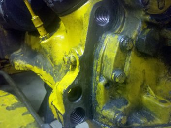
Left side of engine block. 2 inserts and threads in block are missing.
|
Right side. Both inserts are tight, but will be replaced.
|
You might be wondering why I just didn't weld up the holes and start fresh. I considered it. The problem is that welding cast iron is a tricky proposition. Heating up one area of cast iron and leaving the remainder cold tends to induce stress. As the weld area cools, the cast iron has a bad habit of cracking. I've read that the best results are obtained by heating the whole block to over 900\B0F, welding it and then allowing the whole block to cool slowly over 12+ hours. Even if I wanted to strip down a good running diesel engine, it would be quite a task to build an enclosure to heat up the block. If my repairs don't work out, I can either find another block or part out the tractor. I hope this isn't necessary.
|
|
|
1/4" steel holder for bushings.
|
Drilling 31/32" hole.
|
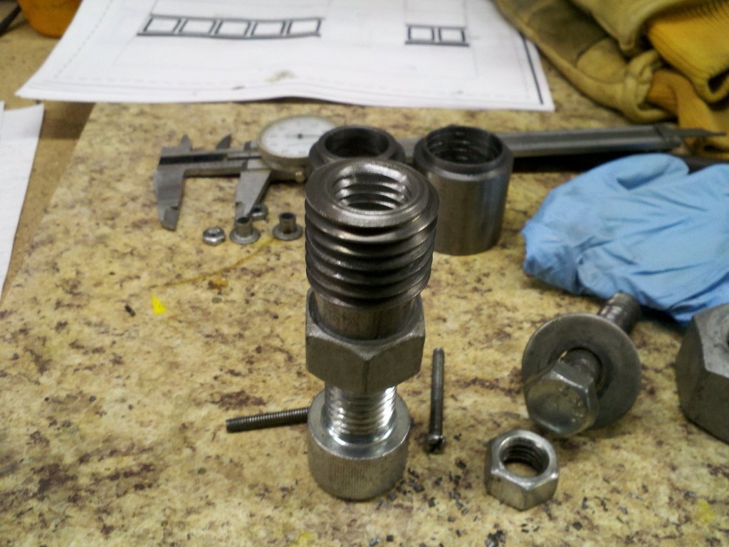
With the holes drilled out and the tapping done, I moved on to turning the 1-1/8" bolts into thread inserts. I cut the heads off of the bolts and chucked them up in the lathe. I faced them flat, then incrementally drilled them out to 21/32" and got the 3/4"- 10 tpi tap started straight. Tapping this large of hole in my little 9" lathe isn't really an option. Yes, I could have single pointed them, but single pointing threads is a lot slower than tapping them. After getting the tap started straight and true, I pulled the bolt out of the lathe and locked it in a couple nuts then secured it in my bench vise. Tapping threads into a grade 8 bolt is a bit tedious. A half turn forward, then a half turn back then advance the tap a full turn to make another half turn of threads. It took my entire body weight at the end of a 15" wrench to tap each hole. I repeated the procedure until the hole was threaded. I used lots of Tapmatic tapping fluid and the threads came out looking pretty nice.
|
|
|
Tap with taper tap, then a plug tap.
|
Two holes were now threaded.
|
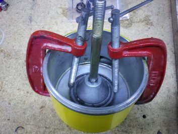
I cut each insert to length on the lathe, then locked each one on to a 3/4" bolt so I could thread it in and make sure that the insert didn't stand proud of the mating surface. With the insert the correct length, I removed it and covered the outer threads with Loctite 277. Once each insert was installed, I made up a mix of washers and assorted spacers to allow me to put tension on each thread insert as the Loctite set up. The instructions said that 24 hours should do it.
After two afternoon's work, I had the inserts installed. The inserts look pretty nice. However, since the job was done pretty much free-hand, I don't know how close I got the inserts to their original positions. Some of this depends on how close the folks who installed the first set of inserts drilled their holes. I guess I will find out when I go to reattach the front end. In the mean time, I have some cleaning to do. There are years of dirt and grime on this tractor that my pressure washer didn't get off before I moved it into the shop. Time to use some Varsol and a brush.
|
|
|
Other side. The hose clamp keeps the bushing a bit tighter.
|
Better shot of tap in the bushing.
|
I got the front of the engine block cleaned up enough to let me see if I have any oil leaks once I get it running again. I also cleaned up the front sub-frame. There was lots of dirt and oil around the front hydraulic pump. I don't know if I have leaks or whether the oil build up was a result of pump replacement prior to me getting the tractor. I guess I will find out soon.
Mating up the sub-frame to block took a bit longer than I had thought it would. I had to drill out a couple of the clearance holes 1/32" larger as the holes must have been a bit off center. It could have been my fault or the dealer's. I'll never know.
|
|
|
Hole is drilled. Ready to add tapping bushing.
|
Tapping the hole with a 24" breaker bar.
|
The torque for the 9/16" and 5/8" original bolts was 130 and 170 foot pounds respectively. Since I had increased the bolt size to 3/4" and was using grade 8 bolts, I could go up to 450 foot pounds. I decided to set the torque to 300 foot pounds which is near the top of the torque of a grade 5 bolt in 3/4". All of the bolts felt solid as I cinched them down - even the one with the shallow threaded insert. So far, so good.
|

|
|
Tapping the inside threads of the insert.
|
Insert mounted on the installing tool.
|
To begin making the side plates, I cut the 1/2" X 6" 1018 steel to 23.5". I held the plate up to the left side of the tractor and looked for obstructions. Since Deere used a 1/2" X 5" plate, I needed to make sure that my slightly larger plate wouldn't interfere with anything. It's a bit of a tight fit around the exhaust down pipe, but it appears that I have a little wiggle room. I marked the location of the holes that would attach it to the flywheel housing, checked them against my measurements and bored the holes on my milling machine.
|
|
|
Keeping tension on the insert while the Loctite sets up.
|
Another insert is installed.
|
I bolted up the plate and marked for the front two holes. I again checked the marked holes against what I had measured and went back to the mill and bored the next two holes. The plate fit well. I then sat down and looked at it for a while.
I am now pretty sure that the JD300 (7320) loader wasn't offered as standard equipment on my 1972 301 tractor. The Deere "where used" lookup on their parts site shows the loader for the 300 tractor, but not for the 301. That said, I have the combination and have no way to tell if it was a later addition. I have gotten one confirmation that another member of one of the tractor forums has the same combination of a 301 with a 300 loader, but he doesn't know if it was a later addition either. His tractor does have the side plates installed and has never had the sub-frame bolts pull out. That makes me feel better about my situation. His side plates are 1/2" X 5" X 23.5". They are held in place by four 5/8" bolts. I was now asking myself if I really wanted to add additional threaded holes or dowel pins to secure these plates.
There is enough room to add two bolts to the sub-frame end of the brace, but only enough room to add one bolt to the flywheel housing end. However, the placement of the third hole in the rear mount would not meet the minimum distance of 2-2/3 times the 5/8" bolt diameter between holes. Best practice is a minimum of 3 bolt diameters between holes. In my head, I went around and around on this matter. After doing some reading about dowel pins, the clamping forces of bolts, bolt single shear loads and I crunched enough numbers to make my eyes glaze over, I finally decided that the clamping force of the four bolts was more than enough to take the load off of the sub-frame to engine bolts. I'd leave it as Deere designed it. I decided to put paint (witness) marks on all my bolts so I could see, at a glance, if any one of them was loosening up or if the side plate was moving under stress.

|
|
|
Two more installed and I'm getting creative on things to use as spacers.
|
The last of the inserts is installed.
|
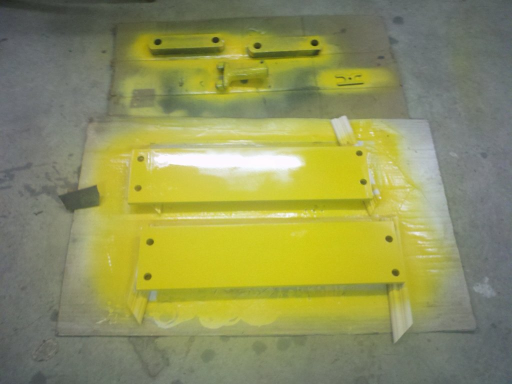
Another afternoon of work got me a second side plate machined up. I did a test fit and was pleased with the results. I filed the edges of the plates and sanded them. I finished them off with a couple coats of "school bus yellow" from Tractor Supply. It doesn't match the old paint perfectly, but it's better than a few other cans I had tried. At some point I will probably repaint the tractor so it's all one color, but I first need to get it mechanically sound.
|

|
|
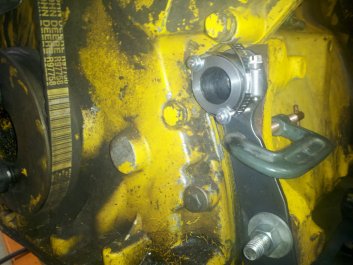
Inserts are installed and the block is cleaned up a bit.
|
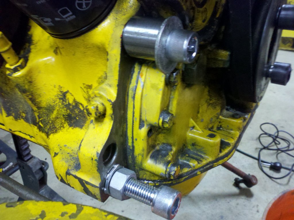
Left side 3/4" - 10 cap screws are installed with heavy lock washers.
|
Today's project is to remove the stuck bolt that holds the right side loader frame to the rear axle. It has been soaking in PB Blaster for a couple weeks, but I really don't expect it to come loose. I may have to resort to using a die grinder to get it free. This is going to be fun. It's in a tight area and there's not a lot of room to work.
|
|
|
Right side bolts.
|
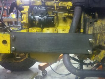
Left side plate is checked for fit.
|
I ended up using my die grinder and an abrasive wheel to cut through the bolt. I almost had to stand on my head to get access to it, but I finally got it cut in two. When I had ordered my parts, I had purchased a new 7/8" bolt to replace it as I was pretty sure that I wasn't going to be able to get it out without ruining it.
The other seven bolts needed some clean up, so I hit them with the wire wheel on the grinder. I also used a thread file to clean out the decades of packed dirt and grime from the threads. They came out looking pretty good.
The next piece of the project was to do some machining on the front loader frame mounts. The mounts are stepped and fit into a stepped area of the sub-frame. Since my side plates would be fitting behind these mounts, the mounts would need 0.5" machined off of the stepped area.
I set the mounts up on the milling machine and cut them down. Fortunately, the way they were designed made this an easy task and should not alter their strength. I was impressed by how fine grained the cast iron was. Milling cast iron always makes a mess, but the chips came off mostly in little curls rather than just making dust. Soon I will be able to start the reassembly.

|
|
|
The side plates get a coat of paint.
|
Rear loader frame bolt cut with abrasive disk.
|
I installed the two side plates and the front mounts. The fit is good and the machined front mounts should allow the loader frame to attach in its stock position. I then began the job of putting the tractor back together.
At some point in the tractor's life, the fan had hit the radiator. This smashed a lot of fins and there was evidence that the radiator had been resoldered in that area. I straightened out the fins the best I could before installing it. I got the radiator back in and attached the hoses. I pressure tested the system while empty and it held pressure, so I added fresh coolant.
|
|
|
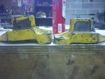
Unmachined mount fits in step.
|
Machined mount with piece of 0.5" steel fits in step.
|
A little later I was ready to fire it up. I hit the key and it roared to life. Literally. There's no muffler. Just a straight pipe. It's a bit on the noisy side. I looked under the tractor for leaks and found one. I immediately shut the tractor down. There was a hydraulic leak from the front right near the three lines that go to the hydraulic pump and oil cooler. I cleaned up the area and called it a night. I'd try to figure out the hydraulic problem tomorrow.
|

|
|
Comparison of unmachined mount to machined mount.
|
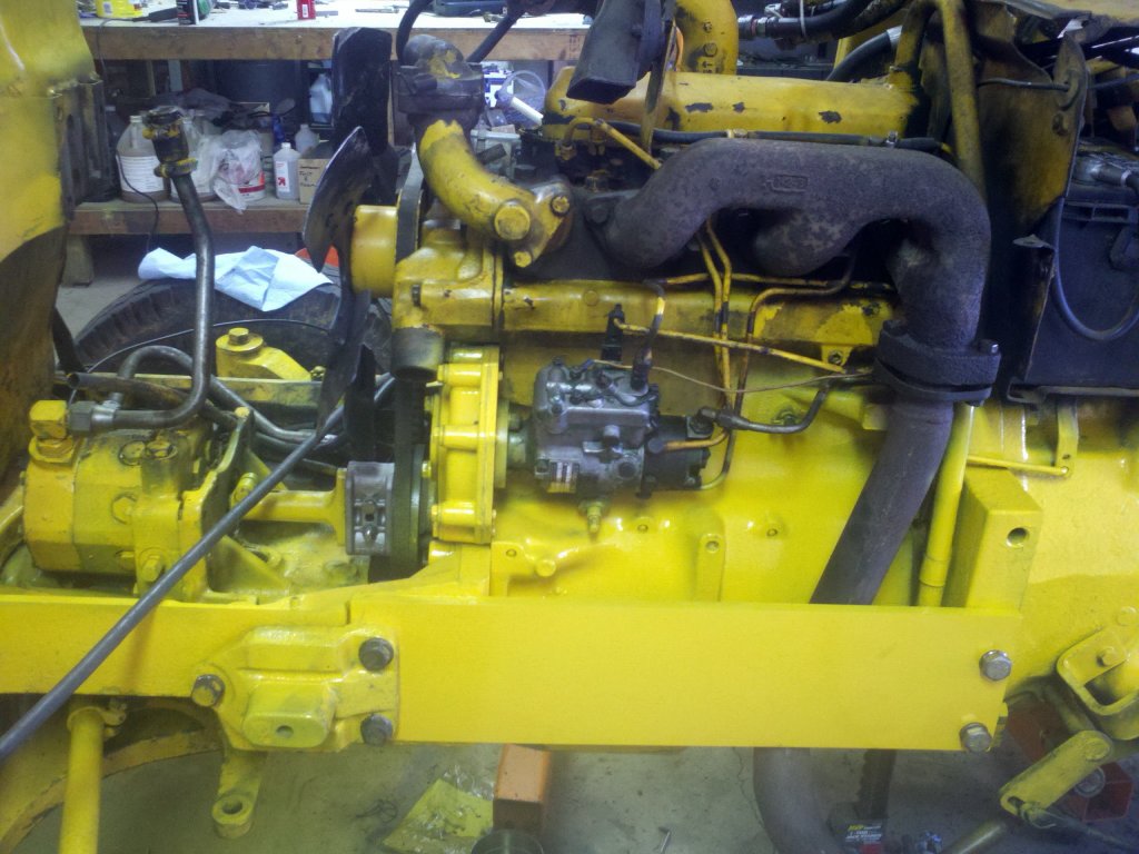
Left side plate is installed.
|
When buying the tractor, I was told that the hydraulics were a bit sluggish and I noticed that when I test drove the tractor. The wet brakes and power steering worked well, but the loader was a bit slow. I had noticed that there was a lot of hydraulic fluid around the area of the hydraulic pump and had planned to look into it. When I pulled the hydraulic lines off to split the tractor, I noticed that two of the steel lines had been cut and recoupled with some hydraulic hose. Not a great repair, but it looked like it had been holding up OK.
|
|
|
Right side plate is installed.
|
Right side loader frame is attached.
|
The third line, the high pressure one, hadn't been cut and had an inline fitting so I just disconnected it there and didn't remove the line from the pump. If I would have removed it, I would have found the leak earlier. This line makes a couple 90\B0 bends where it runs through the sub-frame. It looked like it was rubbing on the edge of the hole that it was snaked through.
To get the line out, I needed to remove the oil cooler. I pulled out the cooler and removed the line. Bingo! The line had been rubbing on the sub-frame and had worn a pin hole through the steel tubing. This should be an easy fix with some brazing rod and my welding torch. I cleaned up the tubing and brazed up the hole. I also added a little material to another area that had been rubbing and was almost worn through.
I reinstalled the hydraulic lines and oil cooler. Feeling a bit more confident, I then serviced the hydraulic system. Drain out the 10 gallons of old fluid, replace the filter and add some new fluid. Deere specified type 303 fluid, but after some research, I found that the stuff labeled 303 in the agricultural supply shops shouldn't be used in tractors with wet brakes. I went with a universal fluid made for tractors with wet brakes. Late in the evening I was able to start the tractor up again. This time there were no leaks.
I didn't run it for too long as it was filling my shop with exhaust fumes, even with all the doors open. I would have finished running and checking it outside, but it was raining and sleeting. Hopefully we'll have some better weather tomorrow.
|
|
|
Left side loader frame is attached.
|
The hydraulic line on the left was rubbing where it went through the frame.
|
The weather in the morning wasn't great, but by the time I got home it was sunny and warmish. Not bad for working outside. I pulled the tractor out of the shop and got to work lubing all of the zerk fittings. I stuck a thermometer in the radiator and started it up. The temp gauge on the dash started to rise, but the coolant temp in the radiator didn't rise as much as the temp gauge. I felt the hoses. The top hose after the thermostat was still cold with the gauge showing normal temperature. I decided to drive it around a bit to see if I could get the thermostat to open. That didn't happen. With a thermometer in the neck of the radiator, I was reading about 180\B0 and saw a tiny bit of evidence that the water pump was flowing, but not what I was used to seeing for a warm engine. The gauge on the dash still read normal, but I would have expected that the thermostat would have opened by now.
I checked my workshop manual and found that the thermostat for the diesel doesn't open until 204\B0. Maybe there's no problem, but I will keep an eye on this until I can confirm that the thermostat is opening and that the water pump is doing its job.
I adjusted the two stage clutch and checked the hydraulic fluid again. It was still a bit low, so I added another couple of quarts. So far, no major issues were found.
|

|
|
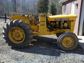
The bucket and arms are finally reattached.
|
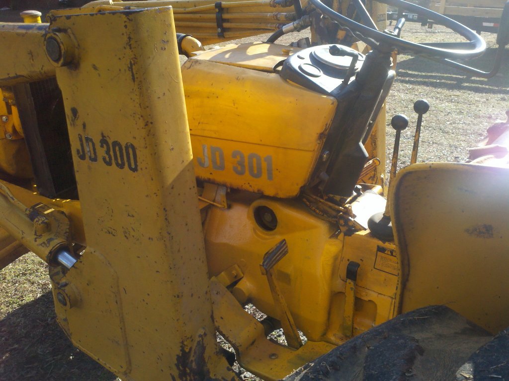
The side panels for the dash were installed.
|
The next step was to reattach the loader and check it for operation. I drove the tractor up under the makeshift gantry and reattached the loader and hydraulics. It wasn't the easiest thing to get the right side loader arm pin installed and I made a mental note to make sure that the tractor was on level ground the next time that I pulled the pins to remove the loader.
Once the loader was attached, it was time for the "all important" test of the hydraulics. Would the loader raise quicker than it did before? The answer was yes. Would it support and hold the tractor off the ground if I put the loader arms down? The answer was again yes.
Would the bucket cylinders raise the front wheels of the tractor off the ground when I rolled the bucket into the dump position? Again a yes. Too cool! From my initial tests, it appears that the hydraulics are working better than when I test drove the tractor. Time will tell, but the results of my tests were better than I had expected.
I've decided to replace the thermostat. After doing some reading, I found that the original spec'd thermostat is set to open at 204\B0. The Deere dealer shows a 180\B0 thermostat as a replacement for the 204\B0 one. Since I'm not seeing any flow at 180\B0, I might as well replace the thermostat with the lower spec'd unit. It doesn't look like the housing has been apart in quite a while. Since I need to go pick up my valve cover gasket anyway, I might as well spend a little more money for peace of mind.
I got the new thermostat and pulled out the old one. It was stamped 205\B0. I cleaned up the housings and installed the 180\B0 thermostat. There wasn't much of a difference between the radiator temperature for the two thermostats with our local temps of about mid-30s in the afternoons, but after working the tractor for a while, there was a little heat at the bottom of the radiator. The tractor's cooling system still seems a little cold blooded to me, but it's holding pressure and it's not overheating, so that's a plus.
While I was road testing the cooling system, I used the loader to move some gravel to fill in some pot holes in the driveway. While I was raising the bucket, I tried to dump it at the same time. The bucket didn't respond for a moment and I let off on the joystick. I tried dumping the bucket again and it dumped. I tried to raise and dump and again, I got a little chatter but couldn't raise and dump at the same time. I remembered reading about this happening if the loader return line dumped into the transmission sump and not to the transmission filter housing.
My loader return line dumped into the sump using a tapped hole at the end of the transmission screen plug. I believe at some point Deere changed to routing the loader and/or service remotes to the filter housing. From what I understand, this was done because the hydraulic supply pump in the transmission has much less output than the front hydraulic pump. When the hydraulic oil is returned from the loader to the sump, the supply pump cannot process enough fluid to keep up with the high pressure pump. This can cause starvation in the front pump. With the loader return line attached to the hydraulic filter cover, the fluid is immediately available for the high pressure pump.
|
|
|
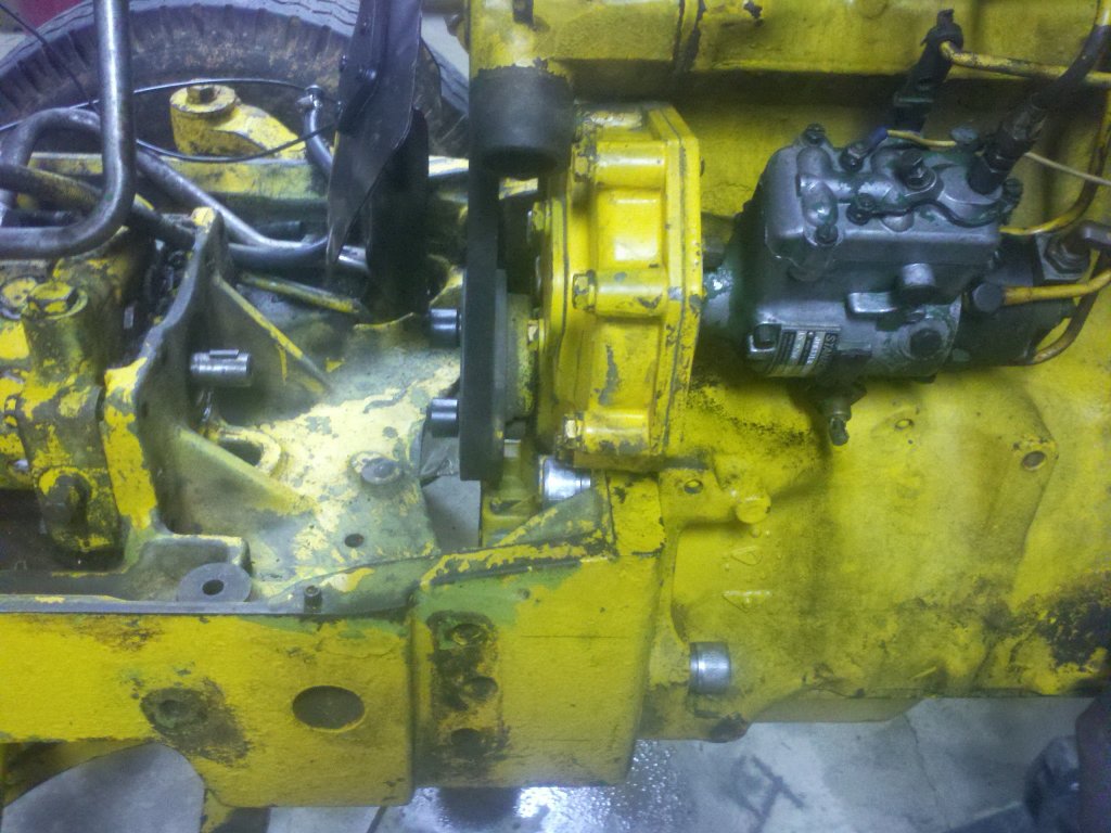
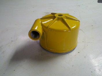
The used ported filter housing.
|
All of the loader hoses were looking a bit worn.
|
When I took a look at the hydraulic schematic in my manual, this made perfect sense. With the return hose plumbed to the transmission filter, the intermediate pressure fluid from the loader return was being added to the intermediate pressure fluid that came from the supply pump. From what I've read, this should make for a better performing loader and keep the high pressure pump continuously supplied with fluid. This has to be a good thing.
I considered tapping a fitting on to the existing filter cover, but found a used ported cover at a used parts place (Wengers in PA) for $50 + 17 shipping (expensive shipping). The added plus is that the ported cover returns the fluid so that it swirls around the filter rather than being directed straight at the filter element if I were to tap a fitting. Many guys have tapped into the filter housing, so I am sure it works, but for $67, I'd rather use the Deere part.
The ported filter cover arrived in two days. Not bad, but still pretty expensive for shipping. I made sure that the port was threaded for a #12 ORB/SAE fitting and ordered a fitting that coupled the #12 ORB to a swivel 3/4" NPTF and also ordered a new return hose. I ordered all 12 of the half inch high pressure hoses that connect to the various parts of the loader. Most of the old ones on the tractor were in pretty bad shape. Since I had seemingly fixed the "slow loader" problem, I might as well bullet-proof the rest of the hydraulics. I seem to be throwing a fair amount of money at this tractor, but much less than any comparable used tractor that I could find locally.
While I am waiting for my hydraulic hoses, I did a little more maintenance. I made an new battery hold down to replace the 15 or so pine boards that had been wedged to hold the battery from moving around. I also cleaned the terminals and sanded the connection for the battery ground strap. I then adjusted the reverser hydraulics screw so that there is less lag between moving the selector to reverse directions. I pulled off various linkages and cleaned them up and added some grease. It's now beginning to feel a little less like an abused machine. I hope that the hoses get here soon as we've made an appointment with the local garden center to come out and give us some landscaping ideas. I'm ready to get some new plants in the ground.

|
|
|
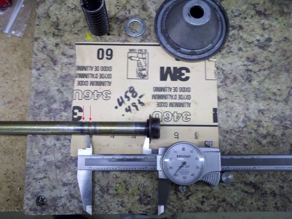
A new groove is cut on the filter bolt to the left of the old groove.
|
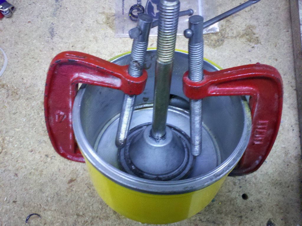
Compressing the spring and cone to install the circlip.
|
< Rant on >
I'm a little pissed at Surplus Center. I ordered my hoses on the 26th and my order sat in the warehouse until the 29th (a Friday) before it said it shipped. I finally got the tracking info and the hoses won't be here until the 4th. I used SC due to some good reviews, but won't use them in the future. When I read the info page at Surplus Center after the order didn't ship for two days, I found that their delivery is listed as 7 to 10 days unless you pay a premium for second or next day shipping. If you're not in a hurry, that's fine, but I can't fathom how they can be so slow. I purchase a fair amount of merchandise from McMaster-Carr. If I order before they close for the evening, I receive my package the next day. (I don't know how they do that, but delivery next day is the rule, not the exception.) I've used Discount Hydraulic Hoses in the past and it's typically been 2 to 4 days from order to receiving the shipment. Not McMaster fast, but acceptable. I considered sending Surplus Center an email questioning their slow order processing, but decided to just "vote with my wallet" and not darken their door again. Live and learn.
< Rant off >
While I wait, I decided to do a little body work. At some point, someone repaired the hood with bondo. Lots of it. Aside from the fact that it was cracking and falling out where something had hit the hood, it was a pretty good job of sculpting. Not a proper repair, but good sculpting none the less. After beating out some of the larger chunks, I remembered that a heat gun could be used to soften the bondo. With a heat gun and scraper, I began to remove bondo. There's a whole lot of it to remove. I figure that I will get the bondo off, then do some metal work to smooth out the hood and give it a spray. I wasn't planning on restoring the finish on the tractor as it will get scratched and dinged as I use it, but I have a little time to kill and I am not a big fan of thick bondo repairs.
I finally got the hoses. They appear to be good quality. I pulled the old filter cover and took a look at the bolt that goes up through the center of the filter and attaches the cover to the trans. It appears that someone replaced the bolt with the wrong one. The 7.5" bolt has a groove cut for the circlip that holds the cone which in turn holds the filter tight against the trans housing. My circlip groove was in the wrong place. My circlip was not engaging in a groove and was just floating on the bolt shaft. I didn't notice this when I replaced the filter a couple weeks ago. In my setup, this is not really an issue as the spring, washer, o-ring and cone sit against the bottom of the filter housing and the circlip just holds these parts from coming apart when you change the filter. However, some tractor models use a circlip to hold the spring closer to the transmission. With the circlip in the wrong place, the filter would not be held tightly against the transmission. This would allow the fluid to bypass the filter. Anyway, my bolt is listed as R82731 and the circlip groove is supposed to be 2.362" up the bolt shaft. My bolt had the groove at 1.968". Judging by the specs, the part number would be L29253 for this bolt. I cut a new groove on the lathe at 2.362".
|
|
|
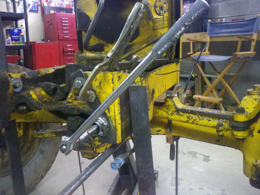
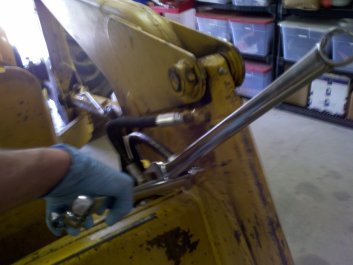
Two wrenches side by side with a third acting as a lever to force the fittings open. Sorry for the blurry pic.
|
The job is done. A little pressure washing to clean the hydraulic fluid off the tractor.
|
I installed the ported filter cover and ran the new 60" return hose up to the controls. I replaced the four hoses from the control valves to the loader with 18" long 1/2" 4000 psi hoses. Eight more hoses to go up front. The next day I installed the rest of the hoses. I found that a few of the 45\B0 fittings on the metal lines had loosened up over the years, so I repositioned them and cinched them down. I came across a couple fittings that were really tough to break free. I used an old mechanic's trick of placing the two wrenches close to each other and used a third wrench as a lever in order to break the fitting free. Since the wrenches and my hands were covered with a lot of slippery fluid, this saved me from busting my knuckles.
I moved the tractor outside and topped off the hydraulic fluid, then pressure washed the tractor to get the hoses cleaned of fluid. Time for another test of the loader.
We've got a brush pile with a few saplings growing out of it. I want to remove it to give the garden a bit more space. The loader was now working much better. I can dump and raise at the same time. I skimmed off the saplings and started to move the pile so that it would be easier to pick it up and dump it into the trailer. I moved some dirt around and picked up a pretty full load in my 5/8 yard bucket. I then drove around for a while and hit every pothole I could find. I rechecked the witness marks on all the bolts I had installed between the sub-frame and engine and they all looked good. It would appear that my repairs are holding up so far.
I still have a lot of small stuff to do on the tractor, but my main goals have been accomplished. The sub-frame appears to be holding and the loader operation is much improved. I am looking forward to getting some landscaping done.
 © Fager April 18, 2013