
|
I'd been looking for a
John Deere number 33 tiller for my garden tractor for couple of years. In my area they come available only once in
a while and they're usually
priced pretty high for their (poor) condition. Since this piece of
machinery weighs a couple hundred pounds, buying one from out of state
isn't really something I'd pay to have shipped. However, I keep hoping
that one will come my way. To increase my chances, I've had a
saved
Ebay search for a 33
tiller for quite a while. I get an email from Ebay when a tiller comes
up within
two hundred miles from me. Not many hits on this search, but I
keep looking.
I was quite surprised when
I received the
email for a tiller with a buy-it-now price of $100. I was more
surprised when the location of the tiller was less than 15 miles from
my home. It even came with the original manual. No questions asked, I
bought it.
I went to pick up the tiller on a Saturday morning. It seems that the
seller had
purchased an old Deere 140 H3 to restore and it had come with an
amazing assortment of attachments. A couple of plows, a rare seeder,
two cultivators, a front
snow blade and the tiller. Since he wasn't interested in gardening, he
was
selling off the stuff he wouldn't use. By selling off the unwanted
stuff, he had already made back more than the price of the 140 and all
the
attachments and was now just looking to make sure that the tiller was
going
to someone who would appreciate it. Yes, that was me. Sometimes I'm
just lucky, but it
did take me a couple years of waiting to land this deal.
It happened to be an early tiller complete with a brass serial tag.
Serial number is 2549, so it's a very early one made for a Deere 140.
The tiller was
made before Deere changed from a 3/4" shaft to a one inch one for the
upper sprocket. The one inch shaft would be preferable, but I'm not
complaining.
 |
 |
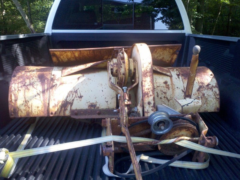
| I finally
have a model 33 tiller. |
A bit rusty,
but a tiller none-the-less. |
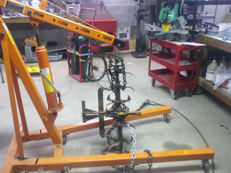
Disassembly:
When Susie and I got home, I used my engine hoist to unload the
tiller and get
it up on the bench. Due to the large amount of rust on the tiller, I
figured that I'd need to start working on the rusted bolts sooner
rather than later. I
spritzed all the nuts and bolts with a mixture of 50/50 ATF and
acetone.
A couple days later I tried some disassembly. Some of the nuts broke
free and some needed more spritzing. When I got to the point of trying
to remove the
bar that sets the attachment width, I found that the outer bolt
came off easily, but the inner one wouldn't budge. I spritzed the
threads some more and waited a couple days and tried again.
I wasn't having much luck removing the inner nut with my open end
wrenches, so I tried it
with a 15 inch adjustable wrench and promptly broke the
spreader bar. Apparently I am stronger than I thought I was (unlikely).
The force I applied with the 15" wrench sheared the bar by the threads
just after the nut. Crap.
However, the situation is not as bad as it could be. The design
of this bar is pretty
simple; 1/2" round stock with a bent end and a
hole for a cotter pin, a U shaped section to go around the pulley nut,
then a long straight section with some 1/2-13 tpi threads on the end. I
figured
that this would be easy enough to make, so I didn't bother looking to
buy one. I later found out that it was no longer
offered by Deere, so I guess I have no choice but to fabricate it. I
proceeded to take apart everything that wasn't rusted stuck.
 |
 |
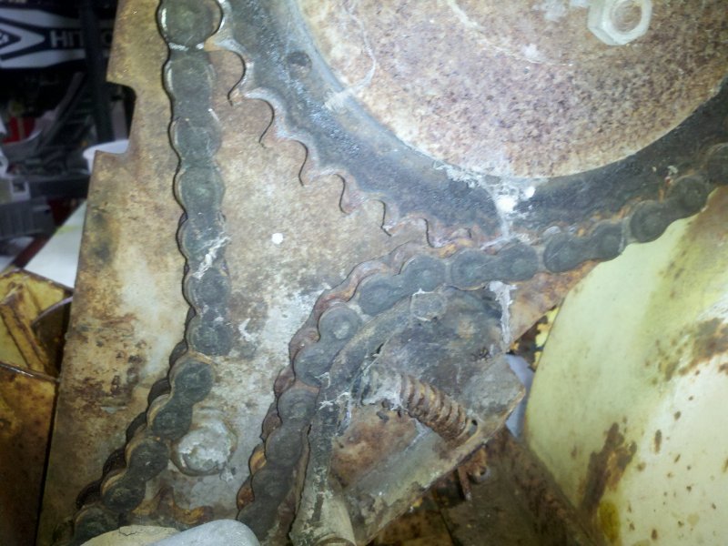
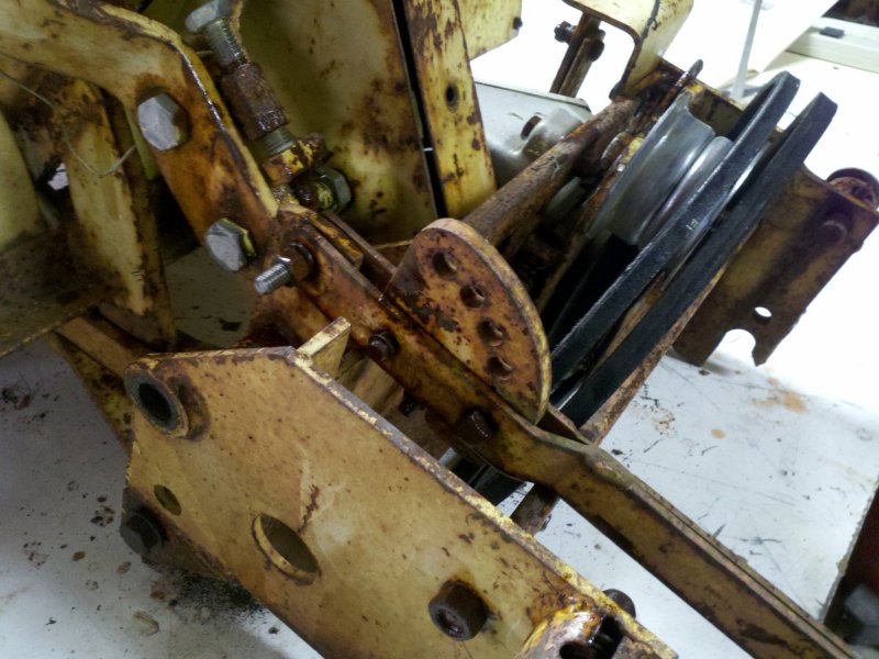
| Although it
doesn't look like it in the picture, the chain tensioner is broken. The
pin that holds the spring has broken away from the tensioner face. |
The tiller
drive chain is dry and stretched and the clutch assembly doesn't seem
to have moved in a while. |
I stripped off the top
chain case and found that one of the clutch
disks was trashed but the rest of the clutch assembly looked OK. I'm
not quite sure what happened to the outboard disk. It looked to me that
the disk hadn't been centered when the assembly was cinched down. The
inside circular bore of the disk had been cut and looked egg shaped
rather than circular. Strange. Whatever the reason that
this occurred, it couldn't be trusted. I
added two clutch disks to my parts list.
More spritzing and some heat from my Oxy-Acetylene torch got the tiller
down to the driven chain case and the tiller tine assemblies. This
tiller has extensions on both sides and I was beginning to wonder
if/how the tine assemblies would come apart.
 |
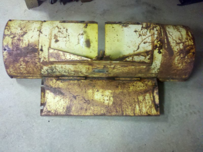 |
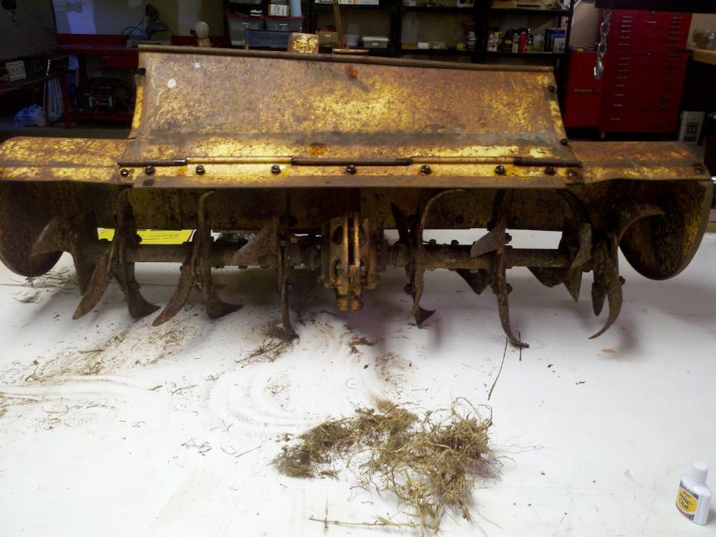
| A little
more rust here too. |
The tiller
shroud needs a little help and has a couple missing flaps. |
The answer is that they
wouldn't come loose easily. Breaking the tine
carriers free of the tine shaft was not fun. In
fact, I'd put it up there with one of the toughest disassembly jobs
I've done on
any mechanical unit and I've worked on a lot of stuff. That said, I did
most of my wrenching in Southern
California and we didn't see too much rust out there, but this thing
was a beast to strip down.
To get started removing
the tine
carriers, I pulled all 4 pins from both sides of
the carriers
after soaking them with penetrant for a few days. However, the
carriers
wouldn't budge off of the lower tine shaft. I tried heat. I tried
and broke
a Snap-on gear puller finger in the process. Darn! I used a big hammer,
heat
and an air hammer. Nothing worked. It was time to do some
research and maybe do some thinking outside the box.
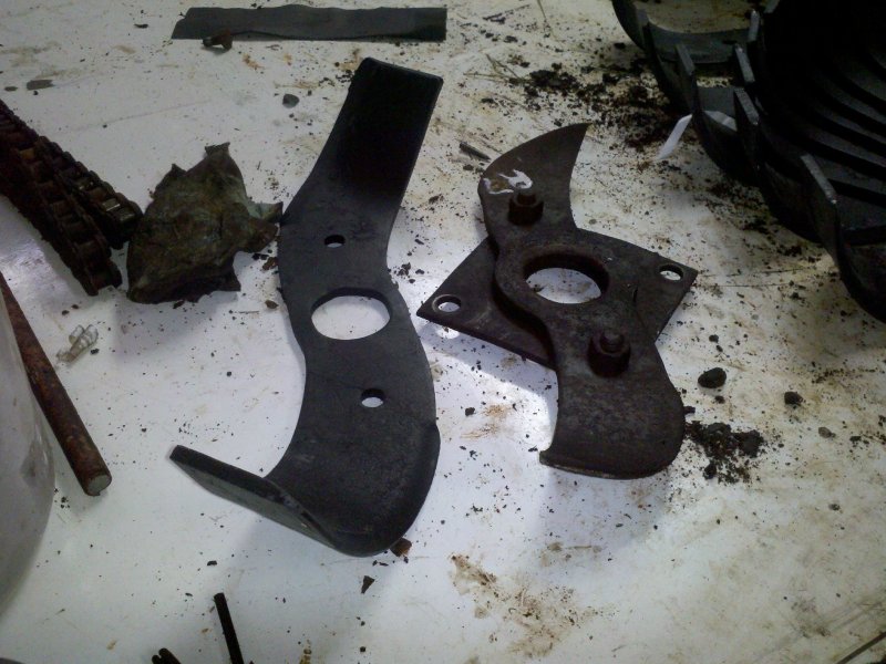
 |
 |
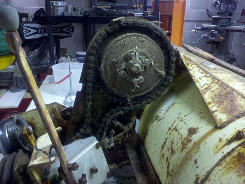
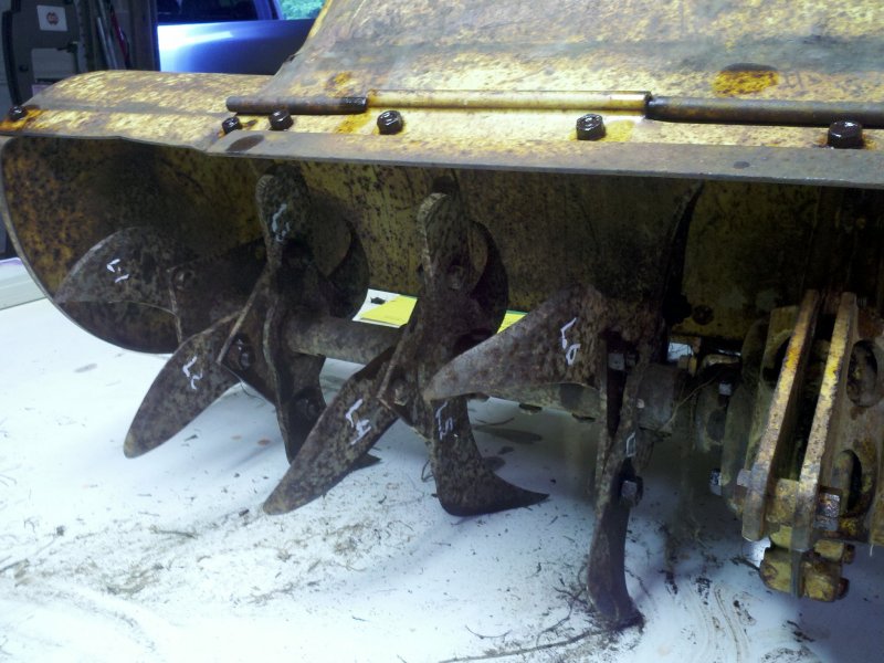
| A shot of
the left tines. |
And the
right. Both sides were really worn out. |
When I did some searching
for possible ways to remove the tine carriers, I came
across what I consider to be a great suggestion. The suggestion was to
till some ground with
the pins that hold the tine carriers to the shaft removed. By putting
rotational strain on the tine carriers, it just
might break them free from the main shaft. Unfortunately, I
already
had the tiller too far apart
to try this.
I ended up hooking up both ends of the tine shaft to my engine hoist
and tried to pull it
apart. No luck initially, but by the third time I heated the tine
carrier to red heat and soaking
it in PB-Blaster and ATF when it cooled a bit, it finally started to
pull
free. More heat and with some persuasion from an air hammer, it finally
popped off. Only one more tine carrier and two more extensions to go.
The second carrier was stuck tighter than the first, but I got it off
with only two heatings. Here's how:
I suspended the tine assembly and chain case from my 2 ton engine hoist
with a chain attached to a long bolt passed through one of the tine
shaft pin holes. I wrapped another chain around the legs of the hoist
and bolted it to the other side of the tine
shaft. By pumping up the hoist, I could put pressure on the tine
carrier against the main shaft. I used the 2 ton position on the
hoist so I could get the most pulling force possible.
 |
 |
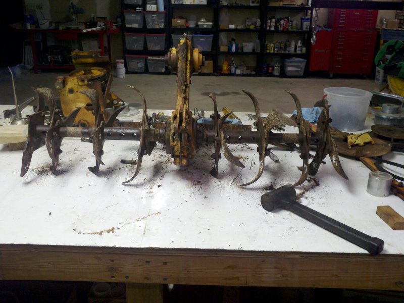
| All I need
to do is pull the tines. |
Using the
engine hoist to exert pulling pressure. |
Cleaning and Repairs
One of these days I will get a media blaster and blast cabinet for the
shop.
I really could have used it on this project. However, one makes do
with what one has. I washed the worst of the grime off the
various parts in a plastic tub, then moved each part into my solvent
tank to be cleaned some more. From there each part was either sanded or
stripped using an assortment of wire wheels and sanders. All of the
parts were then wiped down with Jasco Prep & Primer to convert the
remaining rust into black oxide so that the parts could be painted.
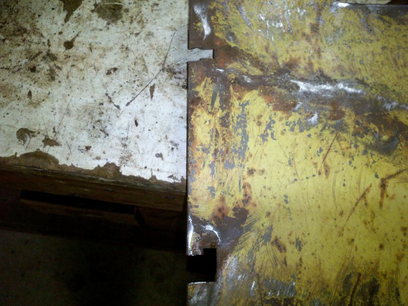
I did have a little sheet
metal repairing to do on the center tiller flap. Apparently the
original
owner had gotten both extension flaps hung up on stumps or what-not
over the years and they had been ripped off. in the process, all four
of the attaching holes on the main flap were ripped out or
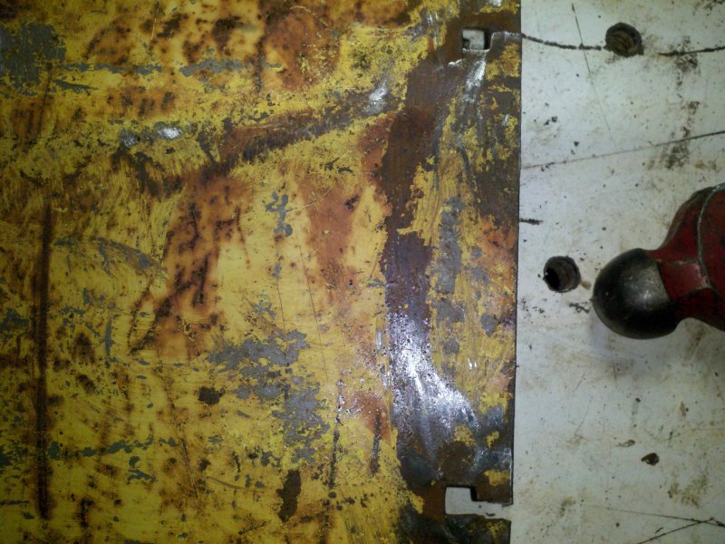
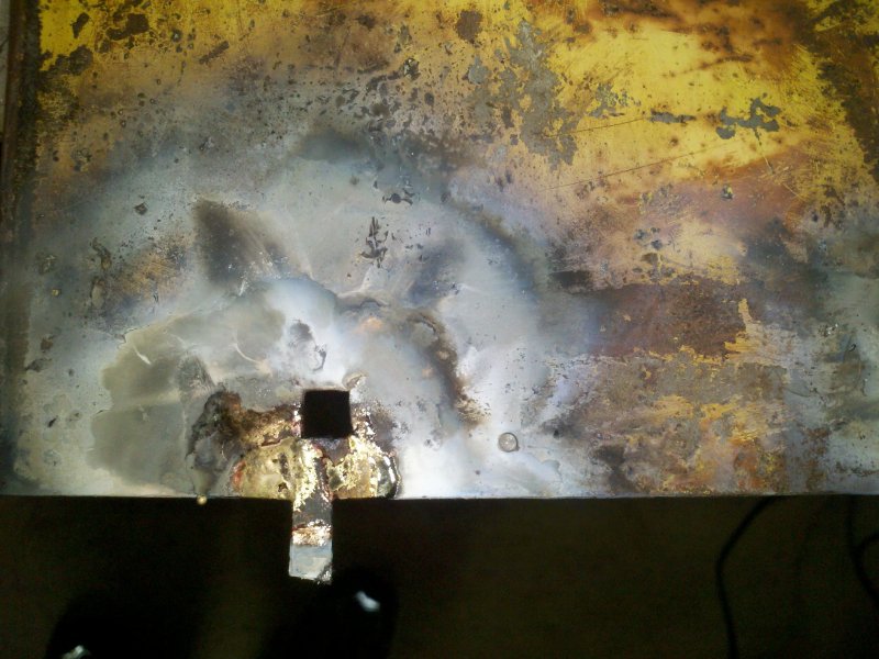
cracked. To fix these,
I cut some
sheet metal of the same thickness as the flap and brazed them in place
to re-form the square carriage bolt holes. I ground the welds down to
(fairly) flat and coated them with Jasco to etch the metal for
painting.
I'm not really as concerned with doing body shop quality finishing here
as I
am with getting the piece to function. After all, this is a
implement that will get pretty beat up by using it as prescribed.
As for the missing parts, I'll look for some
extension flaps, but if none show up, I'll probably make up some
replacements out of the sheet metal I have on hand.
 |
 |
| Broken holes
left side. |
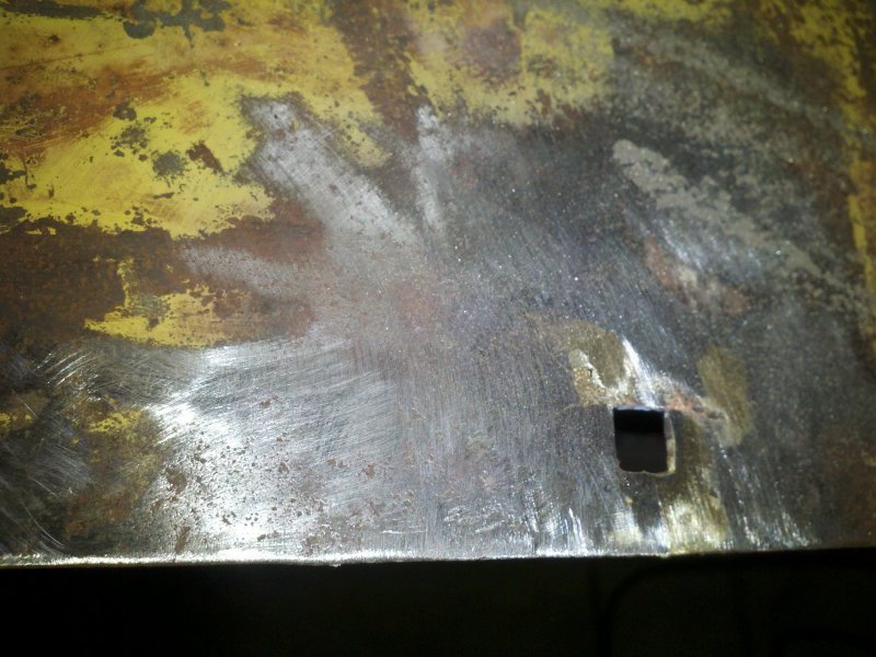
Broken holes
right side. |
 |
 |
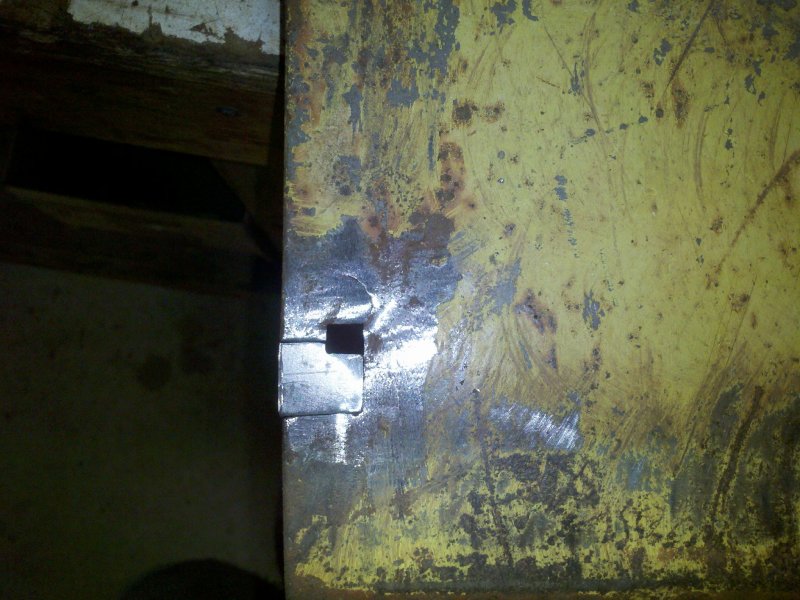
| Sheet metal
cut to fit. |
Another key
cut and flux applied. |
 |
 |
| Key brazed
in place. |
Repairs are
ground down. |
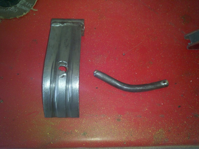
As I said above, the chain
tensioner in the drive case was broken. It also had some pretty deep
grooves where the chain had run along it un-lubricated for quite a
while. My Deere dealer said that this part was no longer
available, so I decided I'd repair it as best as I could. The
semi-circular rod that holds the spring that pushes against the chain
would be easy enough to braze back on. To repair the grooves, I'd fill
them with braze (60% silver), then add a piece of Teflon or Delrin to
make the chain slide easier. Many motorcycle primary chain
tensioners use a facing rather than letting the steel chain ride on a
steel
tensioner. I'm guessing that using a facing and actually lubing
the chain once in a while will make this repair last quite a while.
 |
 |
| Broken
tensioner. |
Tensioner
held in the welding vise. |
 |
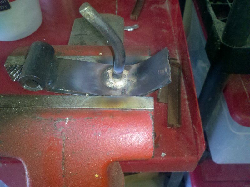 |
| Flux is
added to grooves on tensioner face so I could braze them somewhat flat
again. |
Rod was
brazed to tensioner on both sides. All I need to do now is to
face it with Teflon or Delrin. |
Parts Order
For some of the bearings and the tines I needed,
I decided to go with aftermarket parts where I could to save some
money. Here's the partial list. Note that if you have a later model
tiller with the 1" top shaft, your bearings will be different than my
3/4" shaft model
bearings (SA204-12).
Tiller tines - 7 each (tiller has
both extensions)
http://www.maximmfg.com/
Maxim Mfg. Part No. 130762 (JD PN M43480) right hand tine - price
$15.95 each
Maxim Mfg. Part No. 130763 (JD PN M43481) left hand tine - price $15.95
each
Maxim does carry the
welded assemblies but that brought the price from about $225 to $400 so
I decided to re-use the carrier shafts and just weld new tines on to
them.
Bearings / Seals / Chain / Clutch Disks
http://www.thebigbearingstore.com/
2 - JD9274 Lower ball bearing - SA206-20 --
1-1/4" Insert Bearing Small OD (Pre-lube) $8.70 each
2 - JD9217 Upper ball bearing SA204-12 -- 3/4"
Insert Bearing (Pre-lube) $6.15 each
2 - M42512 Outer angle drive bearing 1630RS
Radial Ball Bearing
3/4" Bore $3.33 each
2 - JD9325 No seal bearings -
inner angle drive bearings - sourced
from Deere $13.65 each
2 - AR90860 Seals for angle
drive - sourced from Deere $11.26 each
#50 Chain and link kits - sourced from Tractor Supply
2- M151902 - Clutch Disk - sourced from Deere $13.10 each
The tiller tines from
Maxim Mfg came pretty quickly after I placed the phone order. I
found that they're not real quick to respond by email, but did
eventually did respond to my email after I had already placed the phone
order. The tines are stamped with the name Empire and look to be
pretty nice in quality. Out of the 14 tines, two on each side
need to be welded to the main carrier and one on to each
extension.
The remainder are bolted on. We'll see how the welding goes.
 |
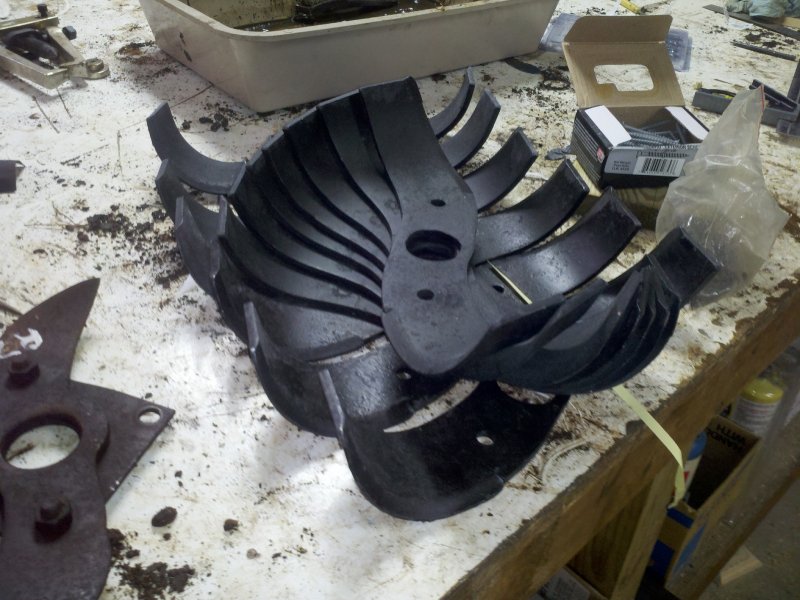 |
| Pretty big difference in size. Looks like the previous owner got a lot of use out of this tiller. | Fourteen
tines - Seven each of left and right. |
Reassembly
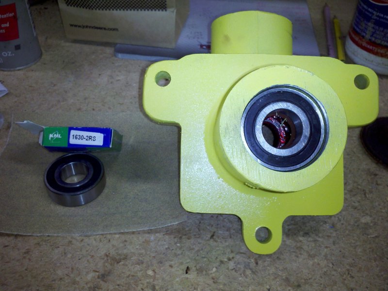
Since the angle drive and main pulley sheave were the last pieces to be
removed, they'd be the first to re-assemble. I had painted the angle
drive Deere yellow, but decided to leave the cover unpainted and just
polish it up a bit.
I started by
installing the two open (unsealed - JD9325) bearings after packing them
with wheel bearing grease. I used an aluminum bearing and seal
installer and tapped them home. Moving from the inside to the outside
of the case, I installed the two AR90860 seals. The new seals were of a
different style than the ones I took out. The old ones had a metal
shell on both sides and the new ones only had the shell on one side.
The
open side (cupped side) is installed toward the inside of the housing.
I
packed some grease in the cupped area and drove them in. The M42512
bearings follow the seals. Again, I used the bearing installer
and tapped them home with a plastic faced hammer.
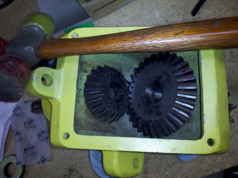
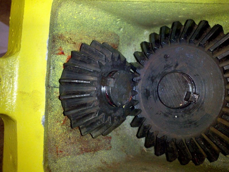
I installed the
center circlips on both shafts and slid them in from the outside of the
case toward the inside. Once the shafts protruded from the inside
bearings by an eighth inch or so, I attached both bevel gears. Do
note that if you install the shafts too far past the inner bearings,
you won't be able to get
the gears on. On my angle drive, 1/8" past the inside bearings seemed
to be the perfect distance. Once the gears were in place, I tapped the
shafts the
rest of the way through. This process would be easier if I had three
hands, but wasn't too bad with the two hands I had available. Once the
gears were seated, I then installed the parallel (square) keys and some
new circlips to
hold the gears in place.
The older tillers
(mine)
call for gear oil as the lubrication of choice for the angle drive and
the newer tillers call for 'corn head'
lubricant. Older units have two ports on the angle drive cover - one
with a 90° pipe fitting to add oil and a pipe plug to check the
level. Newer models have no ports at all.
Right or wrong, I
did something different. I used a mixture of hypoid gear oil - 85w-140
weight and wheel
bearing grease. I used about three ounces total mixed 2/3 grease and
1/3 oil. My reasoning was that
the bevel gears had a bit of wear and the grease+oil would help keep
them a
bit quieter. I also felt that using the thicker mixture would help
prevent
leaks past the seals later in the angle drive's life. I'll let you know
how that works out in a decade or so. Once assembled, the
drive felt silky-smooth when turned. So far, so good.
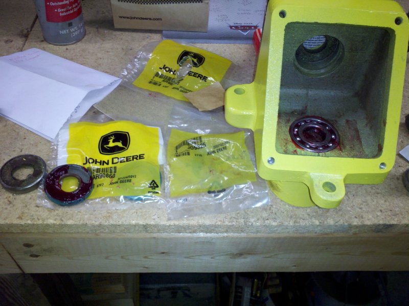 |
 |
| Inside open
bearing is greased and installed. Old seal on left and new one (with
grease) on right. |
Seal is
installed cup side down with bearing tool. A large socket would do in a
pinch. |
 |
 |
| Outer sealed
bearing is installed. |
The process
is repeated for the other bearings. |
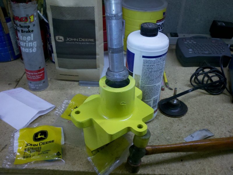
 |
 |
| With the
shafts barely protruding, the gears are added. |
Shafts are
tapped all of the way through and keys are added. |
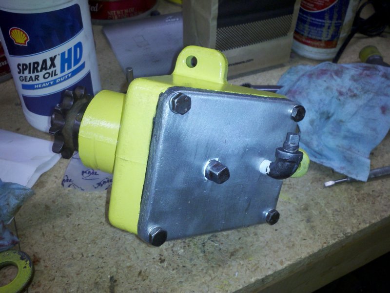 |
| Assembled
and ready to install. |
I still have a lot
to do on this tiller, so I'll be updating this page as I progress on
the rebuild. I am hoping that I will have the
tiller done before the end of October 2012, so I can get started on a
tilling a much
larger garden for next year. We do like the sweet corn we've
grown this year and want much more.
| Tiller Page 1 |
Tiller Page 2 | Tiller Page 3 |
© Fager 8-22-12