|
Repairing a Dodge Ram with the Death Wobble
October 30, 2014
A few weeks ago, our
son called and told me that he now knew what the dreaded Dodge
death wobble was and that it scared the crap out of him. He was
driving at interstate speeds and hit a good sized pothole. The
front end of his 2006 Ram 2500 Hemi 4x4 quad cab started shaking
violently. The only way he got it to stop shaking was to slow
the truck down to around 35 MPH in the fast lane of interstate
95. He finished off his trip in the slow lane driving well below
the posted speed limit. Since that day it has been getting worse
each time he drives it. He asked if I could help him get rid of
the wobble. I asked when he wanted to start work on it.
His truck is lifted a
couple inches in the front using a Rough Country Leveling Kit
[#9219] and he's running BF Goodrich 315/R70/17 All Terrain
tires. I have the same tires but haven't installed the springs
yet. They've been sitting under the bench for a couple years
now. Before we went to the larger tires, we both had read as
much as we could about larger tires and lifting the trucks. In
the process of the research we had come across talk about the
death wobble. We both knew about it, but neither of us had
experienced it. He has about 80k miles on his truck and I have
about 62k on mine. Not a lot of miles on either of them
considering they're eight years old. He does a lot of driving ,
but has a couple of vehicles to split up his driving mileage and
I now work from home and don't drive nearly as much as I did a
few years ago.
While we were over
visiting his family a week ago, I crawled under his truck and
took a look at the front suspension. He only had a short pry bar
to loan me, but I checked for steering play as best as I could
with the tool I had. The track bar seemed a bit too easy to
move, so we'd need to get some new track bar bushings to start
with. He ordered a set of Luke's Link Track Bar Bushings. These
are polyurethane replacements for the rubber bushings that come
on the truck. I also thought that a couple of the tie rod and drag link ends were
suspect, but I would need to do some measuring before I could be
sure of that. We decided that he'd come up to our house once the
bushings arrived and we'd do as much as we could in one day so
that he could make the 120 mile trip back home that same day. He
has his own family now and would rather be with them than spend
the night at mom and dad's. I don't blame him.

|
|
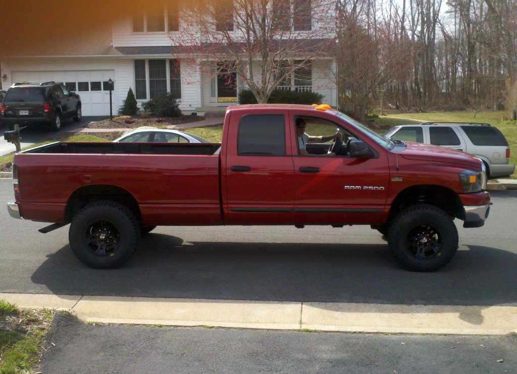
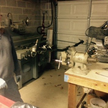
Mike's
truck a few years back when we had just added the
front springs, rims and tires.
|
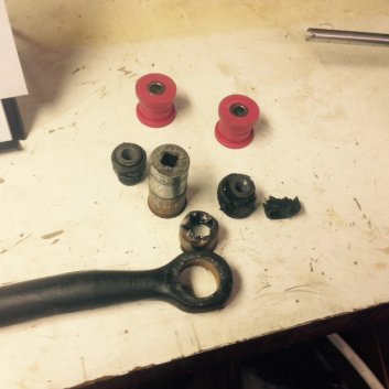
The
old tie rod is held in the vise so we can get some
measurements.
|
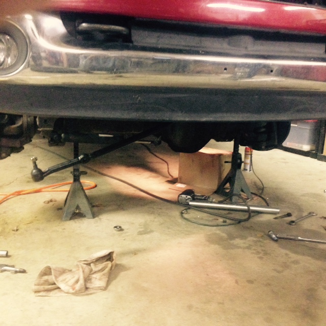
He arrived mid-morning
with the track bar bushings in hand and we got to work. First we
put the front end up on jack stands. One under each side of the
front axle tubes. I did a shake test of each front wheel. I
grabbed the driver's front tire at the 12 o'clock and 6 o'clock
positions and tried to shake the wheel. This is done by pulling
on the 12:00 position as you push on the 6:00 position and then
reversed by pushing on the 12:00 position and pulling on the
6:00 position. Back and forth, back and forth, and repeat a few
more times. I felt some movement, but not a lot. I thought that
this was inconclusive, but warranted further investigation. I
have to say that this is a lot easier if you're working with a
passenger car with normal sized tires. The big 315/R70/17 BF
Goodrich All Terrain tires are heavy and resist being shaken by
anyone smaller than the incredible hulk. As I said, I felt some
movement, but nothing definite at this point. I tried the shake
test again using the 9 o'clock and 3 o'clock positions. This
time there was more movement. There's definitely some play
somewhere that's not supposed to be there. The big question is
where. A certain amount of movement is normal as the steering is
meant to move. If the steering wheel lock is not engaged, you
will see the steering wheel move as you perform this test. For
all but the dealer mechanics, who work on these trucks daily and
know by experience how much play is normal, it is probably a
good idea to lock the steering wheel for this test. With the
wheel locked, pretty much all movement you feel while shaking
the wheels at the 9 and 3 positions will be unwanted
looseness/slop.
We repeated the test on
the passenger side front tire. The results were about the same
on the 12 and 6 o'clock positions, but much worse on the 9 and 3
o'clock positions. OK, we've got some slop, but where? This is
what we would now try and discern. The next test was to get out
the dial indicator with a magnetic base and test the upper and
lower ball joints. My Dodge workshop repair manual gives an
overview of this procedure, but doesn't tell you where you
should mount the dial indicator base. This is pretty typical for
a factory workshop manual. You are expected to know that the
base of the indicator needs to be attached to something that
won't move in the same plane as the part you are testing. After
all, you are a Dodge mechanic and have done this test countless
times, right? Well, maybe. For those of us who aren't
professional Dodge techs, attach the base to some part of the
body that doesn't move with the front suspension. For testing
the ball joints, I found a spot to attach the indicator base on
the sheet metal next to the coil springs. The indicator plunger
is placed on the steering knuckle next to the nut on the ball
joint shaft. The plunger needs to be aligned to the vertical
plane so that when you pry against the ball joint shaft and the
cup that the shaft and ball reside in, you can measure the
amount of movement. In this case it is up and down. With the
indicator set up, I pried between the axle tube yoke and the
knuckle. I got a reading of 0.040". I set the dial indicator
back to zero to the test for the lower ball joint. This time you
set up a jack stand and use it as the fulcrum for your pry bar.
Pry upwards on the flat part of the steering knuckle next to the
ball joint stud and nut using the jack-stand as the fulcrum.
Record your movement. Ours was 0.041". Add these together and it
shouldn't be over 0.090". Our combined reading on the driver's
side was 0.081". Not worn to the point that Dodge recommends
replacement, but close. We repeated the tests on the
passenger side and came up with total movement of 0.087". The
ball joints were testing close to their limit and we discussed
replacing them, but we still had more tests to perform.
|
|
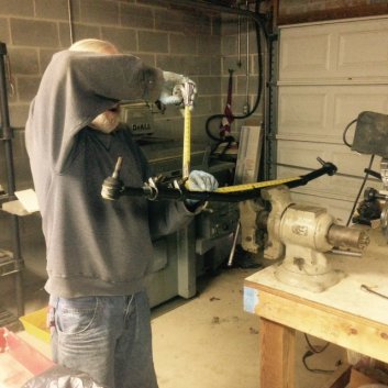
Measuring
how far to screw on the tie rod end so that the new
tie rod is the same length as the old one. I'm not
hiding from the camera... Really.
|
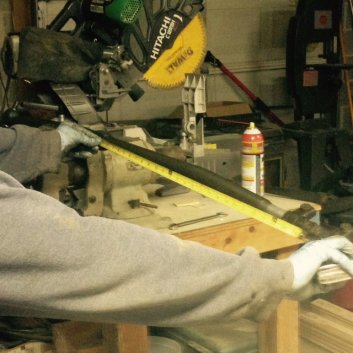
Measuring
the total length so that the new tie rod is the same
length as the old one.
|
Next
on the agenda was testing the tie rod ends. The test
procedure is similar to the ball joints; mount the indicator
base to something that won't move, put the indicator plunger
on the joint side of the tie rod end and use a pry bar to
force the joint apart and measure how much the joint lifts
away from the bolted side. The one thing to look out for is
that the tie rod ends don't swivel while you are trying to
measure them. You don't want them to swivel because of the
possibility that you would end up measuring the swivel
rather than the actual play. You need to use your pry bar in
such a way as to try and force the joint apart without
introducing any swivel in the joint. The driver's side tie
rod end passed at about 0.010". The joints at the Pitman arm
and passenger side tie rod both failed. Both were well over
the 0.020" amount of allowable play. These joints had grease
nipples. I asked my son how often he had been lubing them
and he gave me a bit of a blank stare. Hmm, I guess they
weren't getting enough lube. We discussed what repairs we
wanted to do. To upgrade to the 2008 style steering, we'd
need to replace the steering linkage (tie rod and drag
link), Pitman arm, and the steering damper. This would be
the best way to go as it changes the geometry from the
inverted Y to a T shaped configuration. The T style
configuration is a better design due to the ability to
maintain a constant toe-in measurement as the suspension
travels up and down. The inverted Y style wasn't the best
design choice in my opinion.
The best price I
found for the newer T style components online was $339 +
shipping. From the dealer, it would be more than $500 and we
still didn't know if we were going to need to replace the
ball joints. If money were not a concern, we'd have gone
with the new 2008 style steering setup. However with a new
baby in their household and having just moved, he wasn't
exactly flush with cash. We decided to replace only the
parts that were way over spec and see if that would get him
on the road without the wobble. If not, we'd do the ball
joints as well. We were also replacing the track bar
bushings and the added stiffness of the polyurethane
bushings should help to keep the front end from moving in
unwanted directions. Hopefully we'd be able to make a big
improvement in the wobble without spending a small fortune.
With all of the reading I had done on the death wobble, I
had found that quite a few folks had replaced a lot more
parts without curing the wobble. I was hoping that this
wasn't going to happen to us.
In the
process of stripping down the truck for inspection, we found
that the front brake pads were getting low. We also found
three snapped lug studs on the passenger side front wheel. A
couple months back, he had the truck in for an alignment and
while I hesitate to place blame, the truck came back to him
with the steering wheel off center and the front lug nuts so
tight that we needed a breaker bar with a cheater pipe to
get them loose today. Somehow I don't think they used a
torque wrench to set the lug tightness. They also missed the
fact that there were loose joints in the steering system. I
was not impressed with their work.

|
|
Test
fitting the new tie rod and drag link.
|
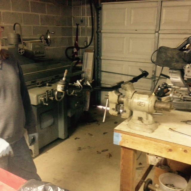
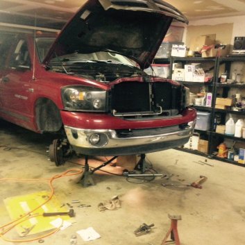
The
shop is just tall enough to handle the truck with
the 315 tires and a small lift.
|
I
was planning to do the alignment myself, in the garage, with
a tape measure to set the toe-in and I had a Joe's Racing
28210 Caster Camber Gauge so we could check and set the
camber and caster. While I will be the first to agree that a
high dollar alignment rack is a better tool for the job, to
get a good alignment, the operator of that machine has to
know and care about the job he/she is doing. Finding a good
alignment tech is much harder than finding a good alignment
machine. I have done many hundreds of alignments on all
kinds of equipment during my time as a mechanic and
considered myself a decent front end tech, but that was many
years ago and I worked on imports not American trucks. That
said, taking alignment readings is pretty much the same on
all cars/trucks. The difference is in how the adjustments
are made. The biggest advantage to having me do this
alignment is that I have a vested interest in making sure
that it is as close as it needs to be. I will also be able
to monitor how the truck drives, as well as monitor the tire
wear and make adjustments if they prove necessary.
Because we were
trying to fix this issue on the cheap, we decided to go with
aftermarket parts. We made up a list and headed to the local
auto parts store. After some trouble finding the right parts
on their computer catalog, we finally thought we had found
the right stuff and ordered it. The Advanced Auto Parts
numbers for the tie rod and drag link were DS1464 and
DWDS1463. It was 2 PM and they said they'd have the parts by
4 PM. We hoped so. It was going to be one of those late
night marathons. Unfortunately, they didn't have stock of
the lug studs and couldn't get them today. At $4.95 each, I
thought they were a bit expensive anyway. We had a couple
hours to kill, so we decided to go to the local Dodge dealer
and get the studs. They didn't have any either and they
wanted almost $15 each. They must be really nice studs at
that price. We finally found them at a NAPA store for a
little under $5 each. I guess that $5 is the going rate.
We headed
back to pick up the steering parts and were pleased that not
only were they there at the time he had promised, but they
looked like the correct parts. They gave my son (who is in
the Army) a military discount and we were on our way home. A
tie rod link, a drag link, and some semi-metallic brake pads
for under $185. Not too horrible.
It was already 4:30
and we had not yet started putting the new parts on the
truck. We were going to be here for a while. Michael got
started doing the brakes and I started transferring parts on
the suspension. The driver's side tie rod end was good, so
it was getting transferred to the new center link that comes
with the passenger's side tie rod end. I measured the
distance between the two tie rod ends and made sure that
when assembled, the total length of the new part was the
same length as the old one. I did the same with the drag
link. Before we installed the steering linkages, we decided
that it would be easier to replace the track bar bushings
without the new parts in the way.
|

|
New
red track bar bushings and what is left of the old
ones after being pressed out of the track bar. The
old socket fits the outer bushing sleeve well.
|
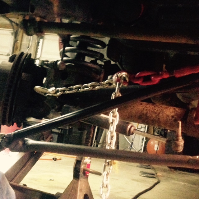
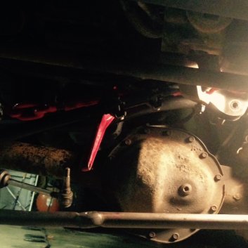
Pulling
the suspension over a half inch. The chain is
attached to the diff tube yoke, then to the
ratcheting chain binder.
|
The track bar is held in by
two bolts; one at each end. The nuts that secure the bolts have
a sheet metal flag welded to them. The flag allows you to
position the nut into a space where your fingers couldn't get to
if you had a nut without this extra long handle. I applaud the
engineer who designed this feature. Without the flag, it would
be near impossible to get the nut positioned. As it is, getting
the passenger side nut centered on the bolt is no easy feat. The
one on the driver's side is much easier. With the track bar out,
we pressed out the rubber center of the bushings on my 20 ton
shop press. The next step was pressing out the thin outer
stamped metal shell of the stock bushings. Fortunately I have a
bunch of old 1/2" drive sockets that get used as press tools
from time to time. This was one of those times. The socket we
chose was almost the perfect diameter, but I got it a little
cocked on the second bushing and flattened out one of the edges.
This required me to use a cold chisel and punch to deform the
lip of the bushing enough that we could then press it through
the track bar. Not a big deal, but another 20 minutes spent on a
job that should have taken five.
Getting the track bar back in was a bit of
a chore. We installed the passenger side first and it took a
while to get that flag nut on the bolt and finally get it
cinched down. When we lifted the driver's side of the track
bar into position, it didn't fit. It was about a half inch too
short -- too far toward the passenger side. Apparently the
suspension had shifted a bit when we pulled out the track bar.
I knew that we needed to pull the suspension toward the
driver's side of the truck and I had a come-along that would
do the job, but I had loaned it out and it wasn't back yet.
What to do? I finally remembered that I had a chain binder
that could serve as a puller. We hooked the binder up to a
chain with one side hooked to the area near the differential
tube's passenger side shock mount. The other end of the binder
was hooked to the body of the truck on the driver's side. A
few turns of the ratcheting chain binder pulled the axle
housing closer to the driver's side and we were able to put
the bolt through the track bar and cinch it tight. Success.
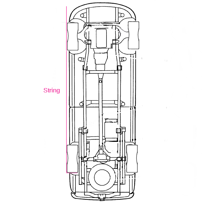
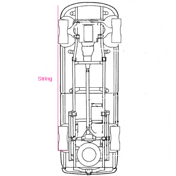
Installing the
steering linkages didn't take long. When we had everything in
place, it was time to align the truck. We let the truck down
off of the jack stands, started it up and more or less
centered the steering wheel. The next step was to get the
front wheels straight with the rear ones. The easiest way to
do this without an alignment machine is with a long string.
Have one person hold the string half way up the rear tire's
tread. If you do this on the rear facing side of the tread and
stretch the string forward to just in front of the front tire,
the string will contact the rear tire's side wall in two
places. Your goal is to get the string to also contact the
same side front tire in two places. Turn the steering wheel
slightly until you have achieved this. Now move to the other
side of the truck and check to see if the string will contact
both tire's sidewalls. Chances are that if you measured the
placement of the tie rod ends correctly, it will be close. If
it is not close to contacting the side wall of the front tire
in two places, spin the adjusting sleeve on the tie rod
(lowest of the two bars with adjusters). One direction will
move the front edge of the front tires farther apart. The
other direction brings them closer together.
|
|
The
hole in the track bar bushing now lines up with the
hole in the mount. The mount is the bright piece on
the upper right.
|
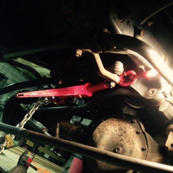
The
chain binder was attached to a gap in the frame on
the driver's side. My come-along would have been
better, but the chain binder worked.
|
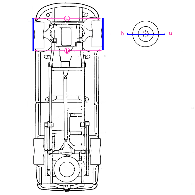
With the front wheels now pointing straight ahead, you
can check the toe-in. For this truck, the spec is 0.10° ±
0.05° toe-in per side. This would mean a total toe-in of from
0.10° to 0.30°. I wanted 0.15° total toe-in which works out to
about a 1/8" difference between the front and rear readings
using the method I will describe. This is a two person job.
You will need two straight sticks that are four feet long. We
used a couple four foot fluorescent tubes. How's that for
making use of what you have? I'll call these sticks just to
make it easier to type. Center the sticks on the wheel so that
the overhang of the stick on each side of the wheel is the
same. The sticks should be parallel with the ground and placed
around the center of the wheel. Place the hook end of a tape
measure over the front end of the stick and have one person
hold it in place. The second person holds his stick and the
body of the tape measure and measures the distance between the
sticks making sure that the measurement is taken on the front
end of his stick as well. Note the reading. Our front reading
was 64 3/8". Now move the tape measure to the rear end of the
sticks which will be behind the front tires. Make sure that
you hook the tape measure to the same relative spot as you did
in the front. Take your reading. Ours was 65". Subtract the
front reading from the rear (65 - 64 3/8). This gave us a
total toe-in of 5/8", which is too much. If the front reading
was larger than the rear, then you have toe-out and you'd want
adjust it until you have toe-in.
At 5/8" total toe-in, we had a 1/2" too much. This means that
the length of the tie rod needs to be expanded to widen the
distance between the front edges of the tires. If your
measurement was larger in the front (toe-out), then you will
need to lessen the length of the tie rod. If I recall
correctly, it took a few turns of the adjustment tube to
remove that extra 1/2" of toe-in. We remeasured again and had
64 5/8" for the front measurement and 64 3/4" for the rear. 64
3/4 - 64 5/8 gives us 1/8" toe-in and this equals 0.15° when
using a 4 foot stick. When you are sure that the tie rod
adjuster has been set to give you the toe-in you want,
make sure that the tie rod end on the driver's side is
centered and not tilted to either side. Hold the adjuster
sleeve tight and spin each of the clamps to where you can
tighten them up and lock the adjustment. You get bonus points
if both the clamps are lined up and pointing in the same
direction. You don't want it to look like you aligned the
truck in your garage, do you? At this point, your steering
wheel may not be straight. You can lengthen or shorten the
length of the drag link, using the adjuster sleeve, to change
the position of the steering wheel. You can go ahead and do
this now, but don't tighten the locking nuts up all the way as
you will want to refine your setting when you take your test
drive and find out what position the steering wheel is when
you are on a flat road traveling straight ahead.
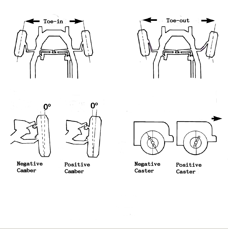
The next step was to check the camber and caster. Camber is
the tilt of the front wheels when you are looking at the
wheels from a viewpoint in front of the truck. If the tops of
the tires tilt toward each other, it's negative camber. If
they tilt away from each other, it's positive. The spec for
the 2006 2500 4X4 is 0.25° ± 0.50° positive individual camber.
You will notice that the plus or minus a half degree means
that the camber can range from 0.25° negative camber to 0.75°
positive camber on each front wheel. I would prefer to see a
small amount of negative camber on a vehicle. To measure the
camber, you just stick the gauge on each front wheel's center
hub, over the big axle nut, level the gauge with the little
bubble level in the end of the tool and take your reading.
Bounce the front end a couple times and check it again. Our
readings showed a hair over 1/4° negative on each wheel.
Nothing needed to be done. Both sides were the same and just a
tiny bit more negative than the Dodge spec. Close enough for
government work.
Caster is the front to
rear tilt of the steering axis. If you could see the ball
joints from the side of the truck, you'd see that if an
imaginary line was drawn through the upper and lower ball
joints it would be slanted with the top of the line rearward
to the bottom of the line. The lower ball joint is further
forward than the upper one. If you compare the truck's caster
angle to motorcycle front forks, a street bike has less caster
angle than a chopper with a long front fork. Both are negative
caster, I.E. the top of the fork is behind the bottom of the
fork. The street bike with less caster is quicker to turn but
gives up some stability at speed. The chopper with it's long
front end (much more caster) is stable as a rock at speed, but
gives up low speed maneuverability. The effect of the caster
angle on the truck is similar, but not nearly as exaggerated
as the example I gave.
|
|
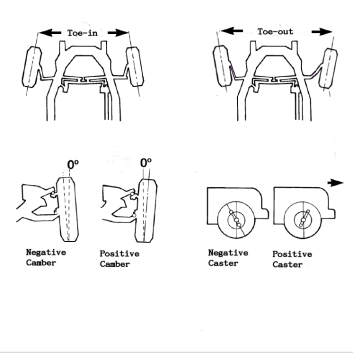
The
three basic settings in an alignment. Toe-in, camber
and caster.
|
Getting
the wheels straight. The red string is held on the
rear tire tread and contacts the sidewall on two
places on each wheel.
|
Checking the caster is a bit
more involved, but with the Joe's Racing camber/caster gauge or
any of the gauges with a magnetic attaching adapter, it is easy.
Note that I did need to modify my gauge's adapter to get it to
fit over the large axle nut. This was a quick job on my lathe
where I increased the diameter of the center hole by about an
eighth inch, but I think that the company also sells a larger
adapter that will clear the nut without resorting to
modifications. If you are going to order one of these gauges,
measure the widest point of the front axle nut and washer and
compare it to the adapter.
To check the caster,
you need to turn the tires about 40° to take your measurements.
The pro alignment machines have swivel plates marked in degrees
that the front tires sit on. This allows you to easily turn the
wheels to their proper position to perform the caster test. I
have no swivel plates, but it's not a big deal. Some DIY guys
use cookie sheets under the tires to make them swivel easier. I
use nothing. The power steering will easily turn the wheels and
when I get to the angle needed, I rock the steering wheel a few
times to make sure that the tire is sitting squarely on the
floor at whatever the chosen position.
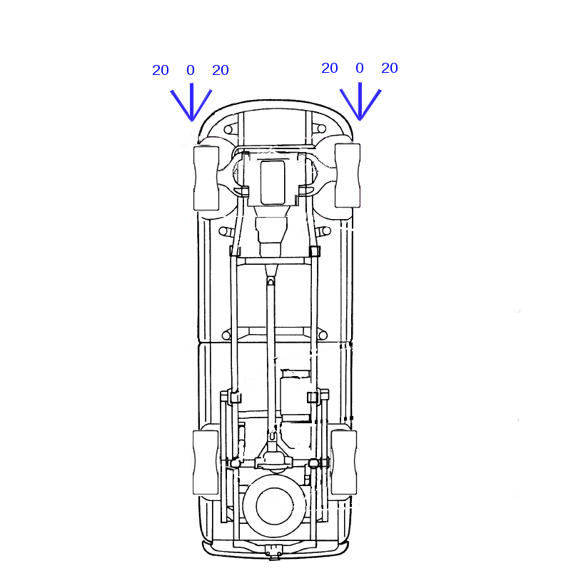
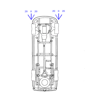
The first thing needed
is to mark the floor to give you the angle references. I placed
a strip of tape on the garage floor in front of each front
wheel. The tape is parallel with the front wheels and extends in
front of the truck about a foot. With a protractor, I placed two
more strips of tape beside the first piece. One starting
directly in front of each tire and extending at a 20°
angle to the left and one extending at 20° to the right. The
three pieces of tape form what looks like an arrow pointing at
the outside edge of each front tire. The procedure for checking
the caster is as follows. Turn the wheels 20° to the right --
parallel with your right tape line. Place the caster gauge on
the center of the wheel over the axle nut. Level the gauge using
the little bubble level closest to you. The caster bubble vial
is the center one of the three. There is an adjuster on it. With
the adjuster, set the bubble to be centered on zero. Turn the
steering wheel so that the right front wheel goes past your
center tape line until it is parallel with the left 20° tape
line. You have now moved the wheel 40°. Check to see where the
bubble is now. This is your caster reading. Ours was 5° and the
spec is 4.5° ± 0.5°. Now repeat the process on the left front
wheel. On this wheel, you start with the wheel lined up to the
left 20° tape mark, then turn the steering wheel to the right
until it lines up with the right 20° tape mark. Again, we found
we had 5° of caster. While the caster was right at the high end
of the spec, I had been thinking about it for a while and was
prepared to try increasing it to 6° if we couldn't get rid of
the wobble any other way. The extra degree might make the front
end less prone to wobble while we looked for other worn parts.
However, for the time being, nothing needs to be changed here
either.
Adjusting the camber
and caster is a little more involved than setting the toe-in.
It's not rocket surgery, but if you've never done it before, I
would advise having a service manual to refer to. There are
procedures that must be followed in order to get the job done
correctly and the adjustments change both camber and caster.
Setting both camber and caster involves moving the position of
the control arms using eccentric bolts in slotted holes. If you
need to adjust the camber or caster, you should recheck the
toe-in after the camber and caster have been set.
As for my thoughts as to why the caster and camber didn't need
adjustment -- it had been set correctly at the factory and
hadn't been changed since then. Unless you whack something
pretty darn hard, the alignment settings don't usually move. The
exception to this is worn steering parts can cause the alignment
settings to change. When you replace the parts, you must check
the alignment. Even though my son has had a recent alignment,
they did not adjust the eccentric cams on the control arms. I
know this because I had marked them with a punch when we had the
front end apart to install his leveling springs. They were still
at the same place I had set them almost 3 years ago and I set
them to where they had been before we loosened the control arms.
I figure that they probably did check the settings, but since
they were within spec, they didn't need to do any adjustments. I
did see one thing that I didn't like that I can attribute to
them. It appears that they had loosened the outboard clamp on
the driver's side tie rod and turned the tie rod end a bit. This
resulted in the tie rod end being tilted rather than being
perpendicular with the tie rod shaft and nut. The tie rod end
should be centered on the steering knuckle and it wasn't. Being
tilted, the joint's range of motion is restricted. This was the
tie rod end that we didn't need to replace, but if we had left
it tilted for an extended period of time, it would have worn out
prematurely. If they were trying to set the toe-in, both nuts
should have been loosened and the sleeve turned in or out to
make the adjustment. The inboard clamp nut had not been loosened
and was very stiff from rust. The sleeve had some rust as well
and hadn't been moved in years. It took a good soaking with some
penetrating oil and working it back and forth a bit at a time to
get it freed up. Anyway, enough of my complaining. I was pretty
confident that our current alignment was darn close and it was
almost time to take the truck for its test drive. We were sure
hoping that we had made an improvement in the wobble.

|
|
Using
two 4' sticks centered on each front wheel, you
measure distance "a" and "b". Distance "a" should be
1/8" to 1/4" smaller than distance "b" for a total
toe-in reading of 0.15° to 0.30°.
|
Use a
protractor to place some tape on the garage floor
marking out 20°, 0°, and 20°. This will give you
marks to line the tires up with when you check your
caster.
|
Before we backed the truck out of the shop, I crawled under the
front end one last time and put a wrench on each nut we had
worked on. Everything was tight except for the two clamps on the
drag link that I had just tightened enough to keep them from
moving until we could do the final adjustments on centering the
steering wheel. Mike backed out of the shop and we headed out
into the night. Before we even got off the gravel road and on to
the public highway, he commented that the steering felt a lot
tighter. It wasn't wandering as much as it had been. We got out
on to one of the back roads and he got the truck up to 50 or so
and hit a small pothole at speed. No wobble. When we reached the
highway, he got it up to 60 and ran over a few more dips and
bumps. So far, so good. No wobbles. After a couple miles we
found a flat, straight place to pull over. He backed up and
pulled forward with his hands off the steering wheel and let the
truck position itself straight ahead. He stopped and I got out
and crawled under the truck with my tools. The steering wheel
was pointing a bit to the right when it should have been
straight. I loosened both the lock nuts on the drag link
adjuster and turned the sleeve until the steering wheel was
centered. I repositioned the clamps and tightened the lock nuts
and we drove some more. The steering wheel was now centered. We
headed back home and cleaned up and called it a day. I asked him
to send me an email after he arrived home to let me know the
outcome of the drive. His two hour drive home down I-95 would
let us know whether the truck was fixed or not. I got an email
saying that it was a pleasant drive home. No wobbles and the
steering felt a lot better than it had in quite some time.
While we have only this one vehicle where we've seen the wobble
and apparently fixed it, I can offer my views on what I saw on
this truck. The wobble was fixed by replacing the worn out tie
rod ends - or in this case - the drag link and tie rod (center
link) that come with those joints. I am pretty sure that
replacing the track bar bushings helped as well. This is all we
changed. His BFG 315 tires are getting close to needing
replacement and the truck doesn't wobble. We did rotate the
tires so the tires that are now up front are nice and flat from
being on the rear of the truck. The tires that were up front
have some edge "cupping" which seems to be pretty normal for
tire wear on these trucks. My BFG's show a little cupping on the
front tires also -- as do the stock tires that now sit in the
shed. The cupping wear on both his and my tires is pretty minor.
You can feel a slight difference in tread height as you run a
finger over one tread to the next around the circumference of
both the inside and outside edges of the tires. Maybe if we both
rotated our tires a bit more frequently, we wouldn't see this.
As I said, the ball joints on his truck showed some wear, but in
this case the wear isn't causing the truck to wobble when
hitting pot holes or bumps at speed. This truck has the old
style power steering box and the steering box shaft that holds
the Pitman arm has a bit of vertical play. My truck which has
less miles and no wobble has the same amount of play in the
shaft so I didn't consider it an issue. I mention these items
because I kept reading that people were replacing these parts
without checking the basics and wondering why the truck still
wobbled. Again, I have only this truck to base my opinion on, so
maybe some trucks don't respond to having worn parts replaced.
We'll keep an eye on the tire wear and I will check the tie rod
ends and ball joints next year to see how they're doing. I am
hoping that with some regular lubing, they will last for a long
while.
As I said, I have read a lot about others' experiences with the
wobble and have read some horror stories of thousands of dollars
being spent and the wobble still remains. Since I haven't been
able to see these trucks, I have to take these stories at face
value. Maybe we just got lucky or maybe the guys working on
these trucks missed something. I don't know. What I do know is
that we tried to approach this repair in a methodical manner and
not just throw parts at it. We found some worn parts, replaced
them, and the wobble went away. I wish it was always this easy.
I also hope that if you are reading this article with hopes of
fixing your wobble, that you have the same outcome as we did.
© Fager October 30, 2014