
|
 |
 |
| Manual
steering
gear
with
right
side
up |
Left
side
with
attached
arm
and
a
little
body
rust |
 |
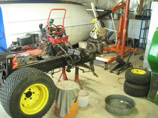 |
| With
the
body
off,
it's
time
to
pull
the engine. |
It's
even
easier
than
yanking
an
old
VW
bug motor. |
 |
 |
| Everywhere
I
look,
parts
are
covered
in
dirt.
I wish I would have borrowed a
power washer and cleaned it before moving it into the basement. |
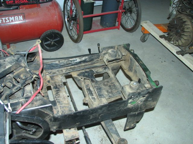
The
steering
rock
shaft
is
removed
and
checked
for play. Both
bushings are pretty sloppy, but it won't be used with the power
steering. |

© Fager 11-20-10