I had been toying with the idea of stripping the 317 down to the frame and doing a full on restoration, but after much thought, I decided that I didn't want this tractor to be a trailer queen. I would strip it down as far as it took to make sure that all the mechanical components were in A1 shape, but I'd just sand and paint the frame rather than strip, media blast and give it a class paint job. My aim is to put this tractor to work and I don't want to have to worry about scratching up a too pretty tractor. The first week of work involved stripping things down and listing what I needed to replace. I am in the habit of replacing nuts and bolts that are rusty and there were a lot of these to count, measure and list. As I progressed, I found some more questionable work by some previous owner. Nothing show stopping, but evidence that whoever was doing the work didn't know or didn't care about doing things correctly.
On the plus side, when I pulled the motor out, I found the source of a squeak that I had been chasing around the front of the engine for a couple weeks. It was one of those noises that seemed to come from different places depending on where you stood. It turned out that the right bracket that attaches the engine to the motor mount was rubbing on one of the allen head bolts that goes into the oil filter block-off plate. The fix was to use a bolt with a little thinner head. As I removed the sheet metal from the engine, I finally found a couple repairs that were obviously done by a craftsman. It appeared that heat from the muffler and vibration caused the sheet metal to weaken in a couple spots and crack. These cracks had been expertly repaired by brazing. It would have been an inexpensive matter to order some used 317 sheet metal from Ebay, but I thought the repair added some character. I just cleaned up the sheet metal and sanded it smooth, then gave it a coat of black semi-gloss.
When I got to the point of removing the operator's station, I found the answer to my ammeter question. It's the darnedest thing. The ammeter has no electrical connections. All it has is a molded area where the charging system wire is held close to the rear of the ammeter. As the system charges and discharges, the current flow in the wire creates enough of a magnetic field to move the ammeter needle. Whoever was in there before me forgot to snap the wire back in place. Once I reattach it and get her running again, I'll be curious to see how well it works. I have a tool for tracking down electrical problems that works on the same principle, but I've never seen anything like this in a vehicle before.
 |
 |
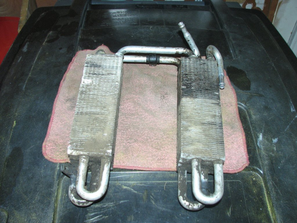
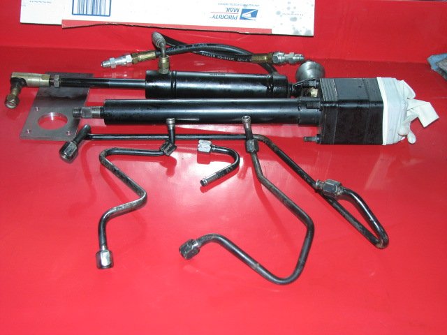
| Parts
for
adding
power
steering
to
the
317 |
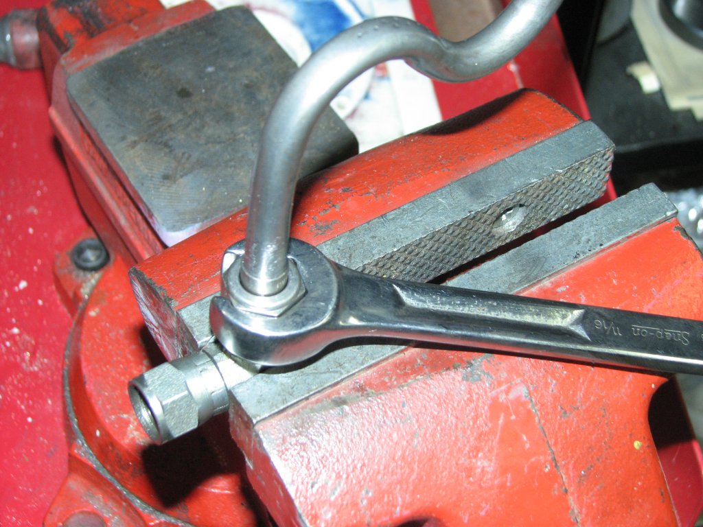
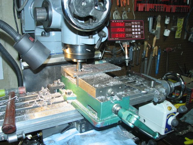
Using
a
fly
cutter
to
cut
the
1.75"
center
hole |
 |
 |
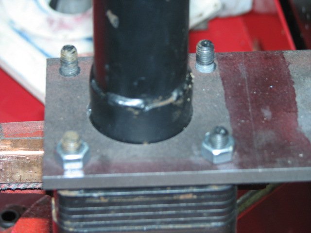
| Test
fitting
the
first
bracket |
First
bracket
drilled,
milled,
bent
and
brazed |
With the operator's station sheet metal off, I removed the steering gear and the rock shaft that transfers the motion outside the frame to the drag link. I had seen reference to rock shafts in my reading, but didn't have a clue what they were. I know of nothing in the automotive trades that I have ever heard called a rock shaft. Once I saw how it worked, I understood the name. Rock shaft could be also called a rocking shaft or a shaft that only spins part of a revolution. It rocks back and forth and has nothing to do with stones or granite. I learned a new term. I cleaned the steering parts up for storage and then started measuring and drawing up ideas for a power steering controller mount. I decided that it needed to be bolt-on so that I could put the tractor back stock configuration if I chose. The other considerations were the angle of the steering shaft, both fore and aft and side to side. Vertical on the left-right plane wouldn't work as the factory manual steering mount was about 3/8" too far to the left, but I could get it close. It also needed to be high enough that the power steering lines didn't interfere with the drive shaft. Remember this, as I didn't. I used a protractor and some cut cardboard to make a template, then cut some 1/4" cold-rolled steel to fit the steering box. I left the mount end of the steel extra long so I could adjust for height. I measured and drilled three holes for mounting to the tractor, then threaded them 5/16" - 18. Last, I drilled three holes in the tractor's bracket, then made them into slots so I could adjust both side to side and height.
 |
 |
| So far, so good. A slight lean to the right, but OK | The
bracket
is
very
strong.
No
movement
at
all. |
 |
 |
| The
operator's
station
fits
like
it
should. |
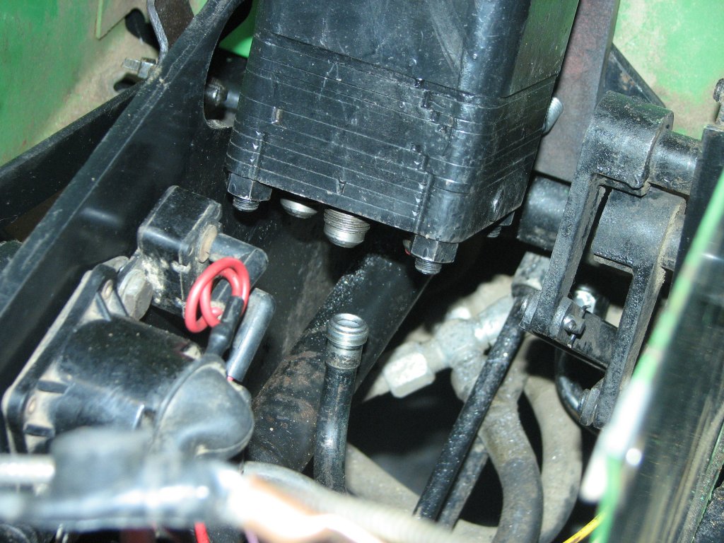
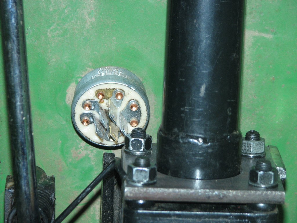
The
controller
just
clears
the
ignition
switch. |
I cut an 1/8" notch across my mount to use as a bending guide, then heated and bent the steel to the proper angle. I cut and brazed a side support on to the bracket and then brazed up the notch I had created. This mount should be strong enough to support my full weight without bending. I sure don't want it bending if I am hanging off the tractor while trying to pick up something off the lawn.
I mounted up the new bracket and steering controller and fit the operator's station. Everything looked good. Again, this was going too well.
 |
 |
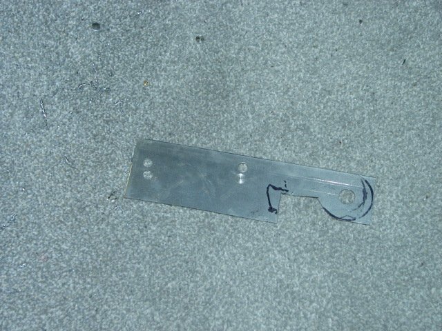
| Sheet
metal
template
to
get
holes
right
for the ram |
1/4"
steel
shaped
and
drilled |
 |
 |
| The
bracket
is
test
fit
using
stock
mounting holes |
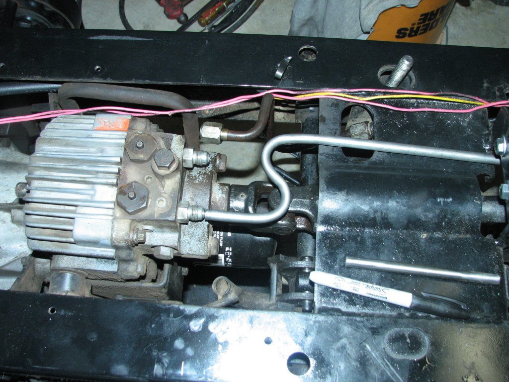
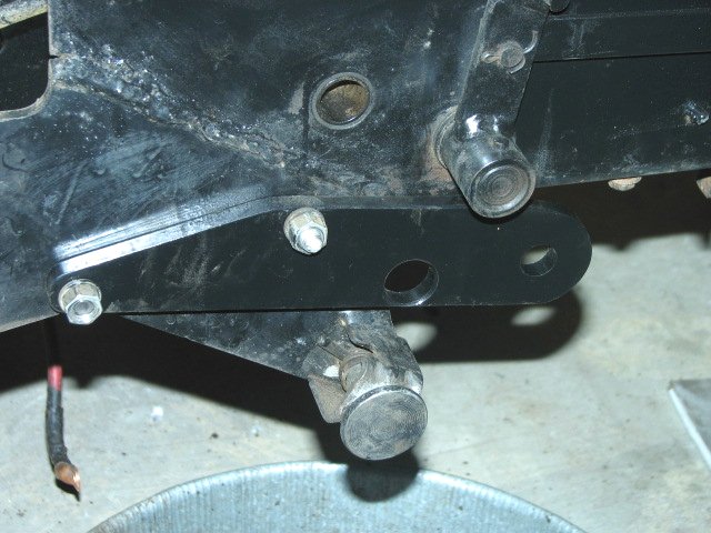
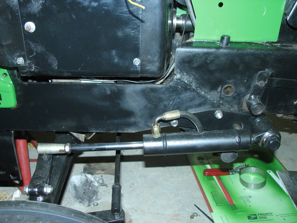
The
steering
ram
is
mounted
and
checked |
I made up a thin sheet metal bracket for mounting the ram and tested it. When it appeared that I had the clearances correct, I made a bracket from another piece of cold-rolled steel. The ram bracket mounted into the same holes used to hold the middle deck mounting pins. I checked to make sure that my mount held the ram exactly half way extended when the front tires were in the straight ahead position and that at full extension the wheels were turned full left. I also checked to make sure that with the ram retracted, the wheels were full lock right. Everything looked good.
I had purchased a used set of 318 hydraulic lines to adapt to the 317. The one between the auxiliary steering controller port and the lift controls worked perfectly. The others, not so well. As I bent a new line for the controller left output port, I discovered that I couldn't get the 90° bend as tight as I needed to clear the drive shaft. Crap! First problem and it's a winner. I worked on this line for a couple days and finally got the bend tight enough by making my own tubing bender on my lathe. I was hoping that this would solve the problem, but it didn't. The problem now was that in order to fit the JIC fitting to the end of the tubing, I needed about a inch of straight tube to clamp in my flaring tool. One inch of straight pipe before the 90° bend, put the bend right into the drive shaft. I was going to need to make a new controller bracket and raise the controller up a bit higher. Double crap. I hate having to re-do a job.
 |
 |
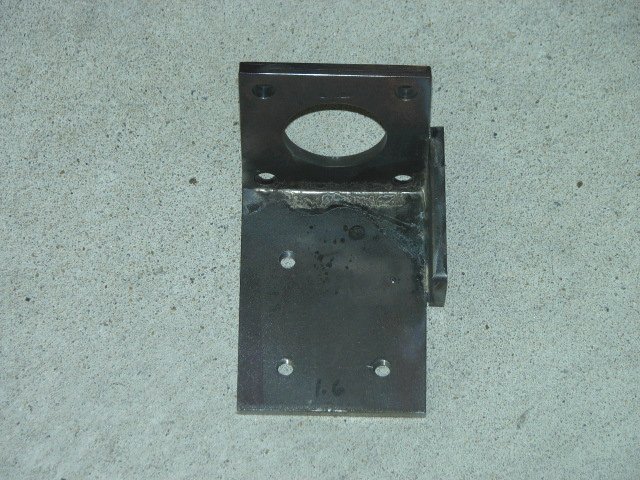
| Second attempt at making the bracket. The holes for the controller are offset to the right side of the tractor to get it as close to the frame as possible | The
bracket
had
a
channel
cut to aid in bending. Once it was bent,
the channel was brazed and a gusset added for rigidity. |
 |
 |
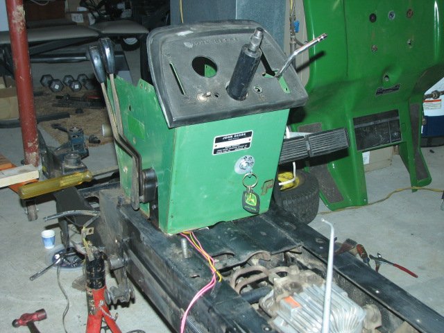
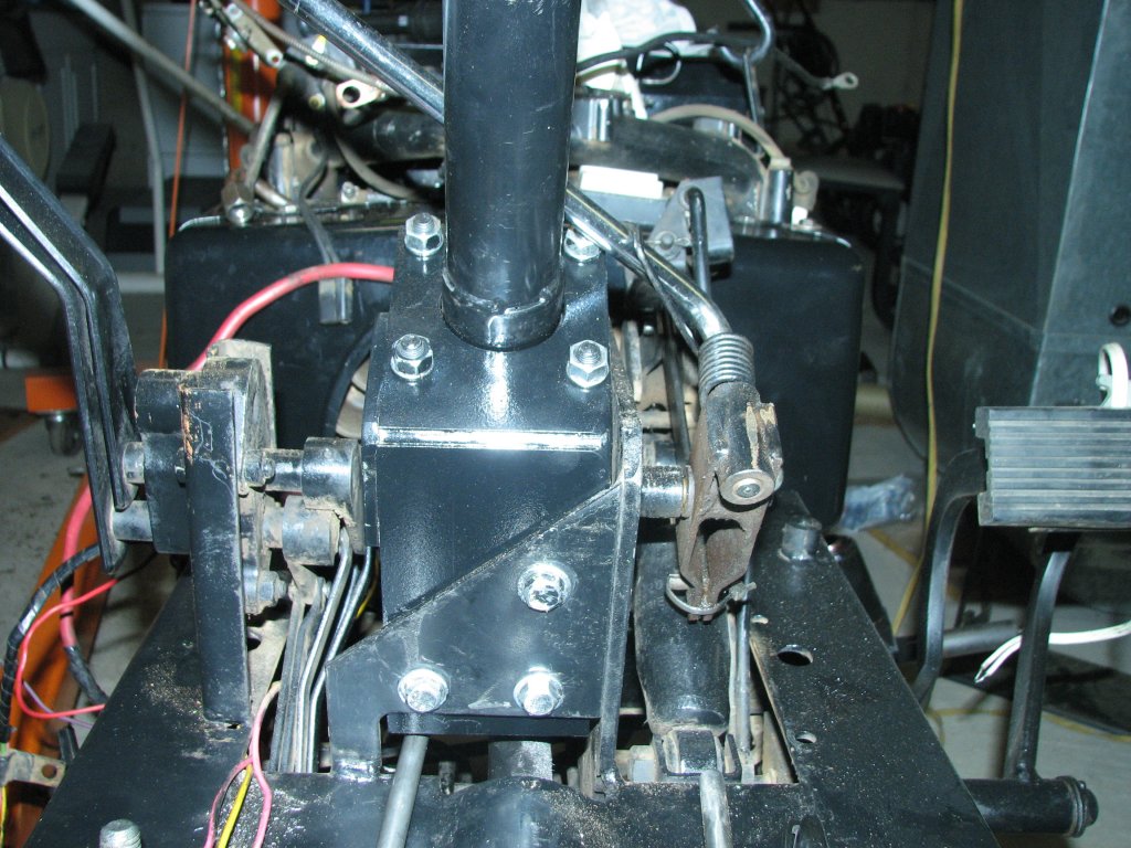
| The
controller
now
sits
further
forward and about 1/2" higher than the
first one. While the front to rear angle was easy, getting
the side angle right wasn't. |
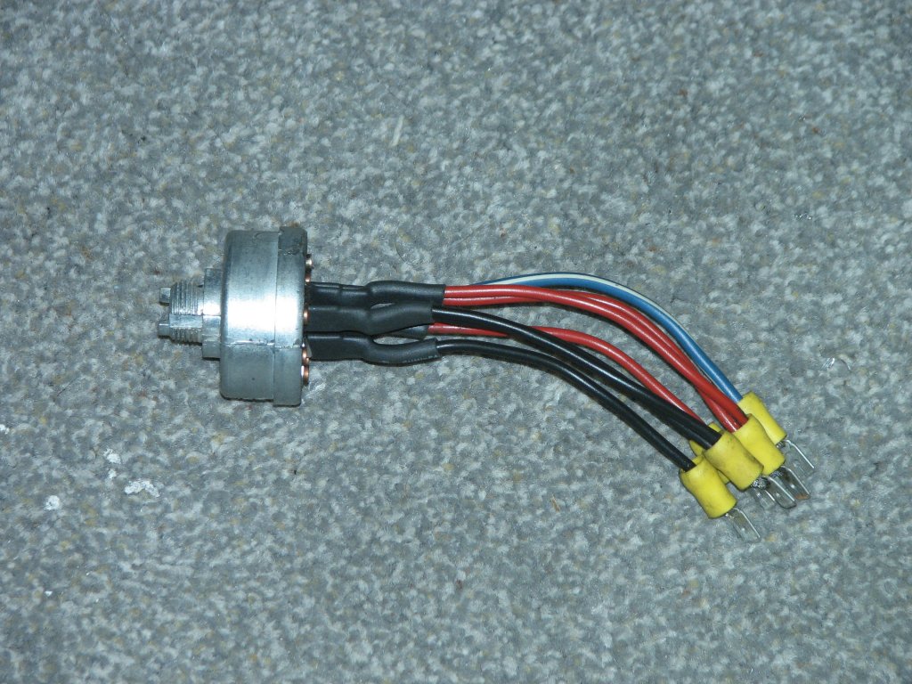
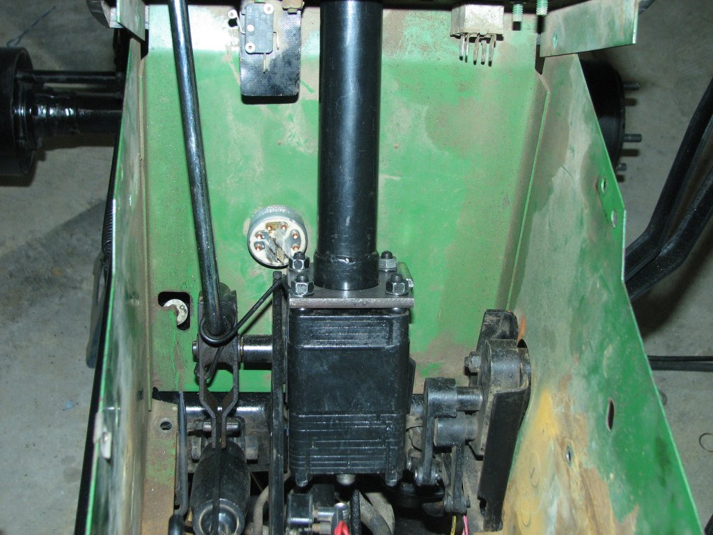
In
addition
to
the
controller
being a little further left, it is also very
close to the ignition switch. I decided to relocate the plug to
prevent future issues |