
|
 |
 |
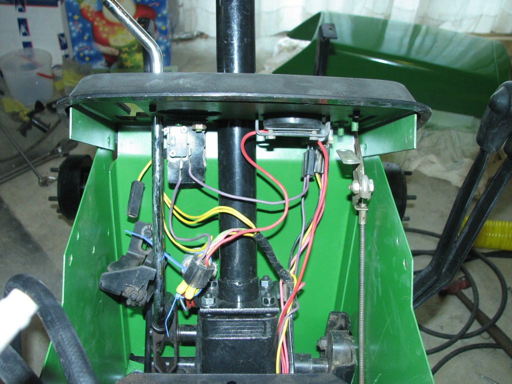
| Ignition
switch
rewired
and
ammeter
hooked
up |
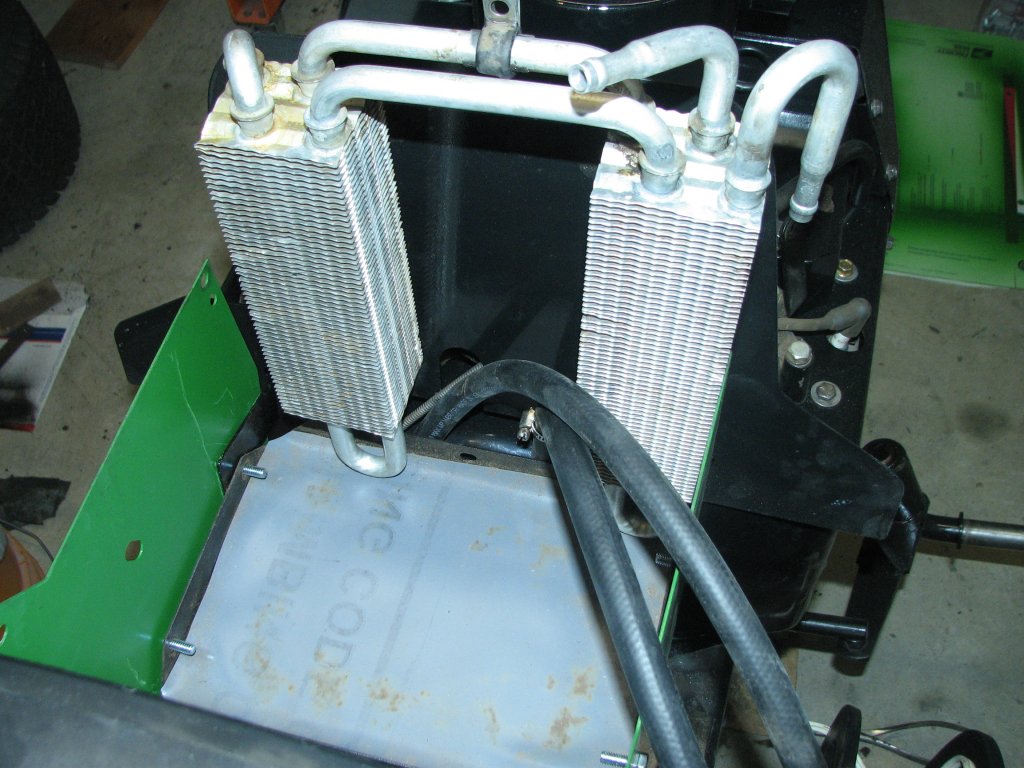
Test
fitting
the
cooler.
Need
to
cut
battery pan. |
 |
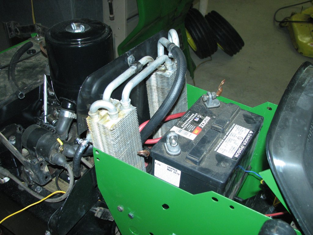 |
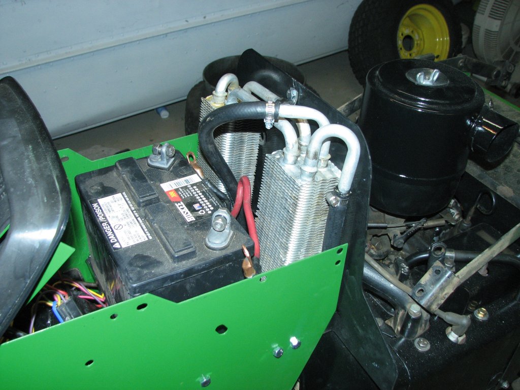
| It's
a
tight
fit,
but
it
does
fit. |
I
hope
it
gets
enough
air
flow.
I'll know in summer. |
 |
 |
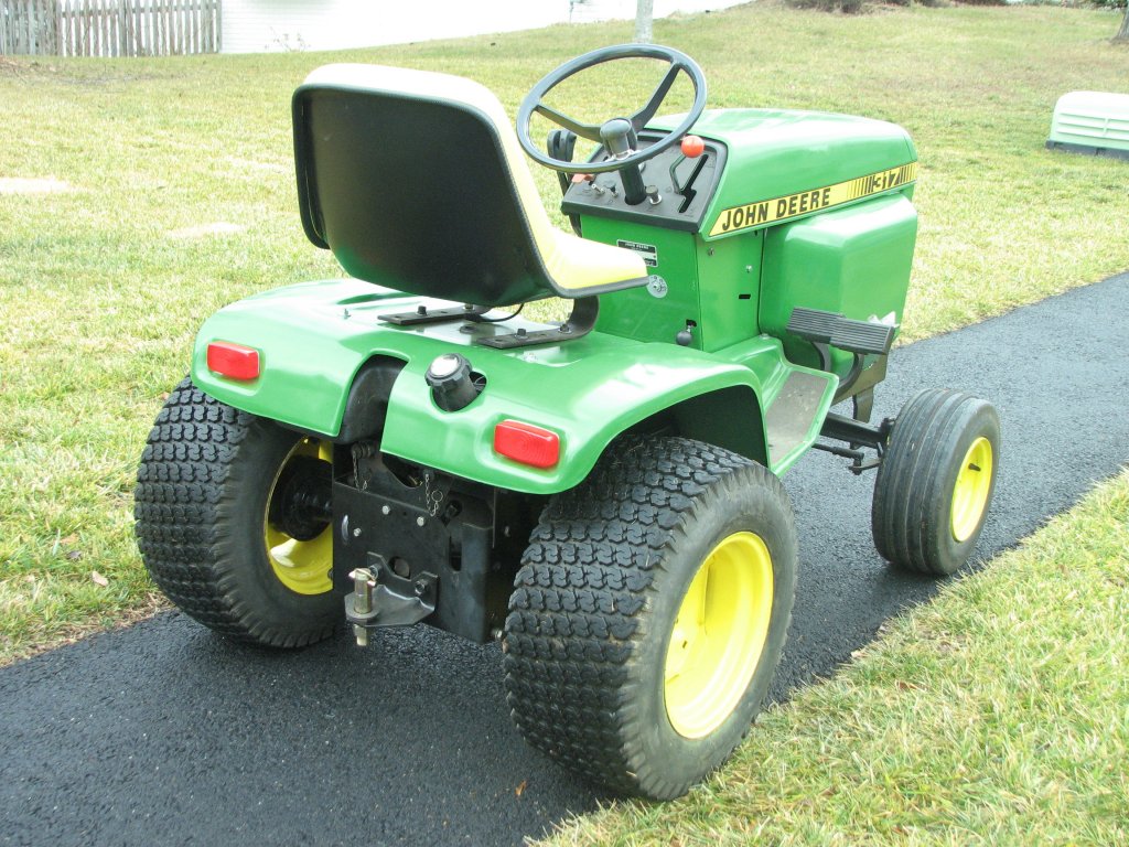
| I
hope
it
remains
as
trouble
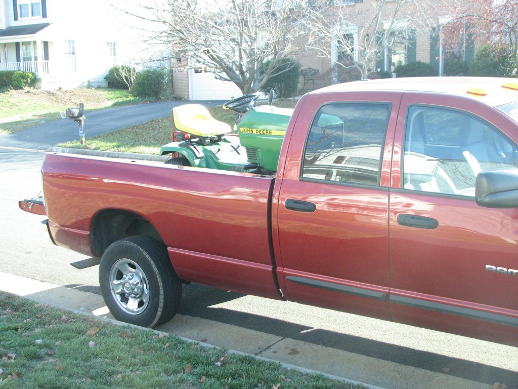
free for my son. |
Loaded,
tied
down
and
ready
to
move. |
 |
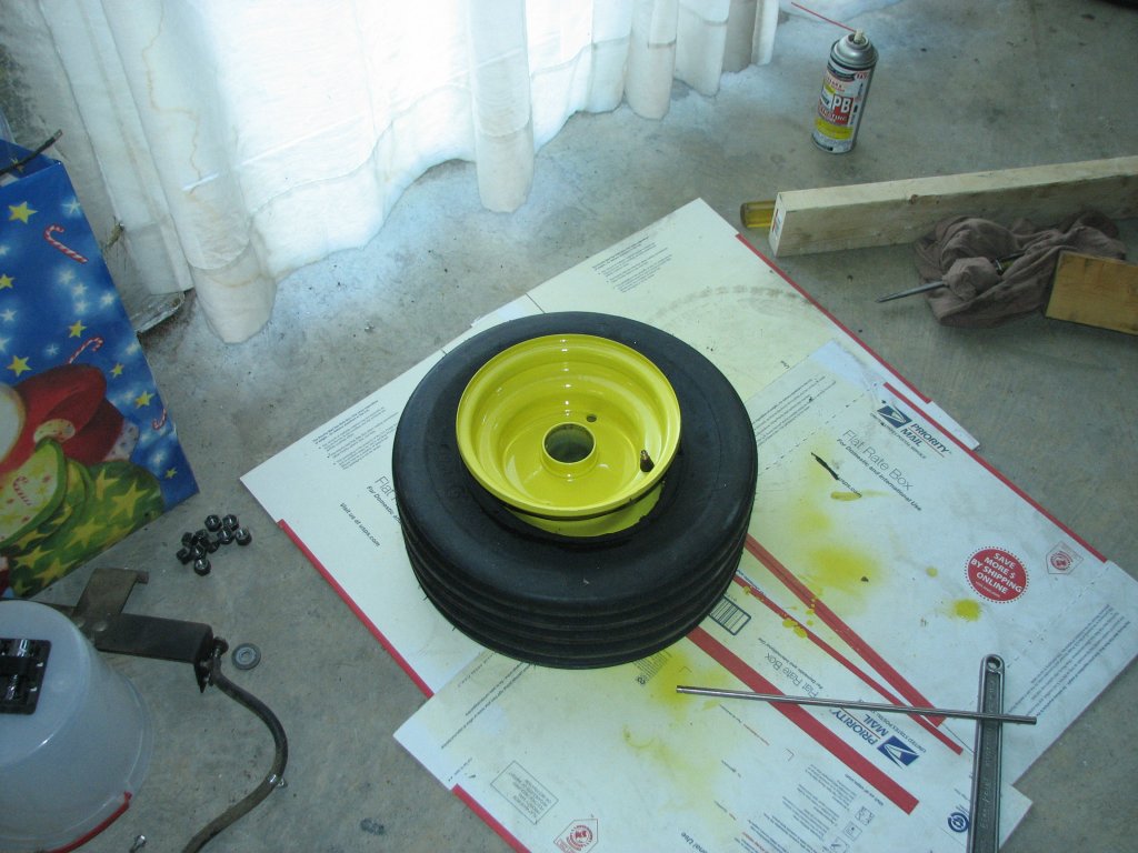 |
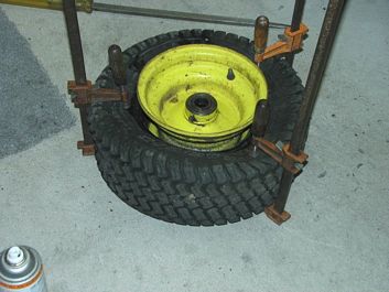
| Dismounting
the
front
tire with a few clamps. |
Getting ready to seat the bead on the V61 front tire. |
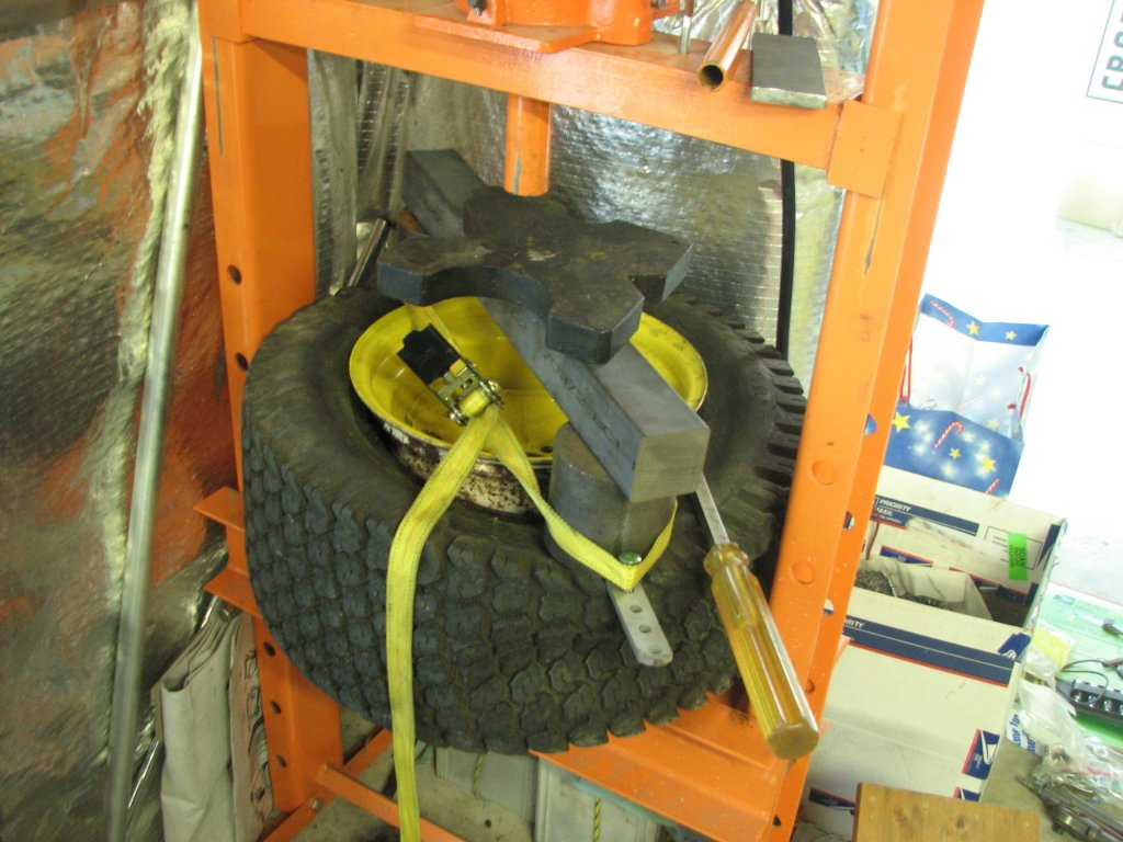 |
| Breaking a rear tire bead. It
may look like a mess, but it
worked. Not a fun job. |
 |
 |
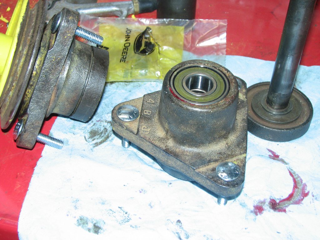
| New
bearings
and
carriage bolts. |
Brushed
on
some
JD yellow, then a spray coat. |
 |
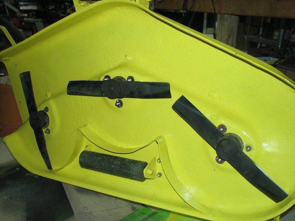 |
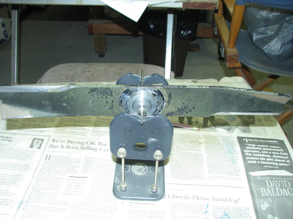
| Balancing
the
blades
with a prop balancer. |
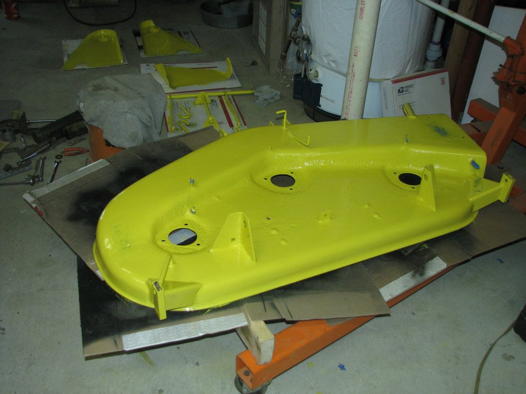
It
certainly
looks
a lot better than it did. |
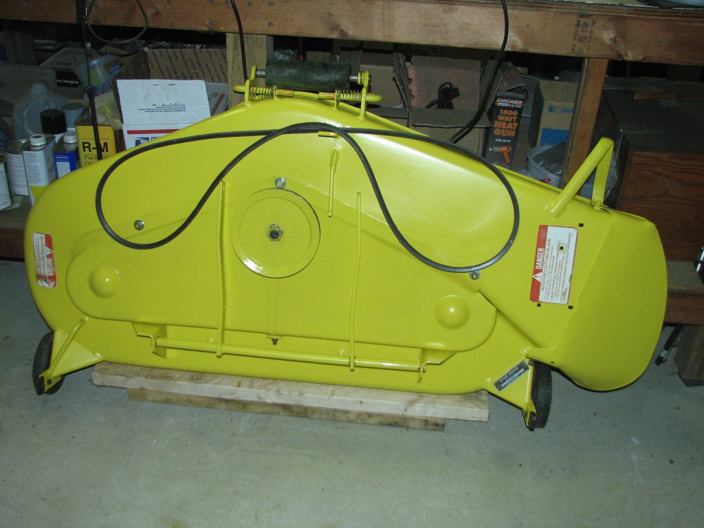 |
| The deck is finished and just
waiting for the grass to grow again. |
 |
 |
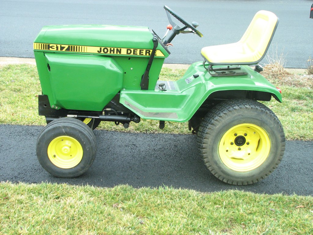
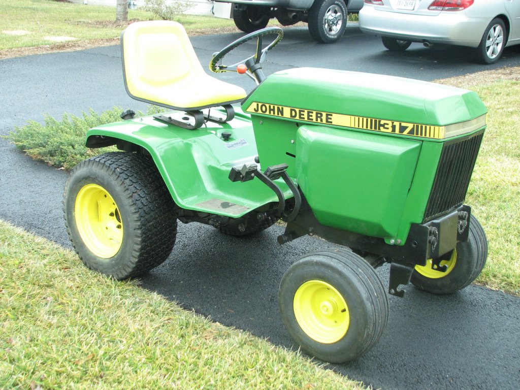
| The
power
steering
looks pretty stock. |
I
really
like
the look of the V61 tires. |
 |
 |
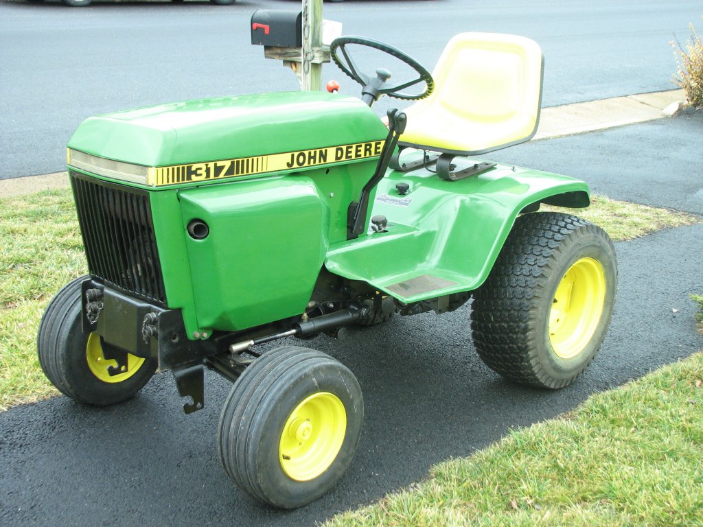
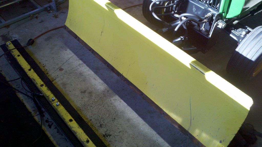
| Next
step
is
to find a front blade. |
A
3-point
hitch
and a tiller would be nice, too. |
 |
 |
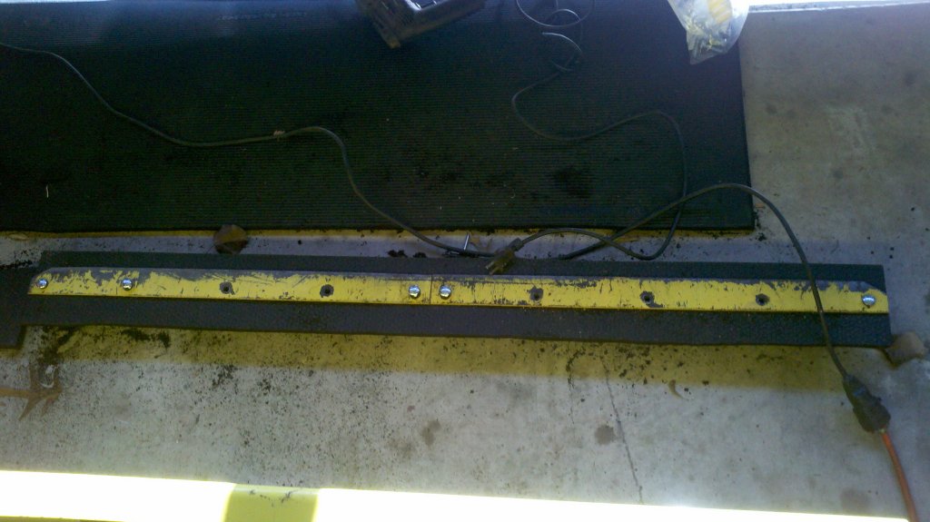
| A
5"
wide
strip was cut from the mat with a jig saw. |
Holes
were
drilled
so that strip can be reversed |
© Fager 1-16-11