Rebuilding
a
Deere
33
Tiller
-
part
3
September 26, 2012
Slipper Clutch
When I disassembled the slipper clutch, I found that the outboard
clutch disk was in bad shape. The inner hole was egg shaped and it
appeared that the disk had not been aligned on whatever kept it
centered in the clutch pack. I figured that it might have been
assembled wrong, but put off judgment until I had the time to focus on
it. Now was the time.

|
|
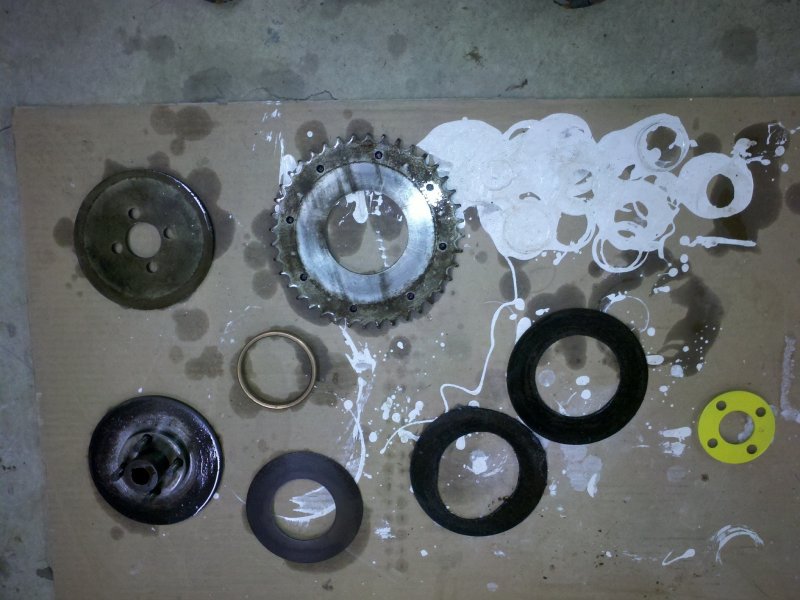
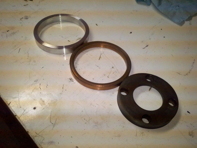
Fresh from
the solvent tank. You can see the egg-shaped hole in the one
clutch disk.
|
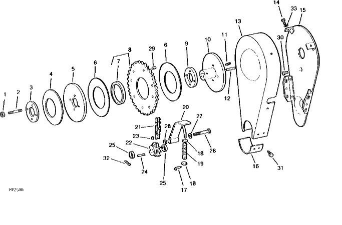
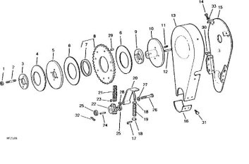
The Deere
parts diagram for the clutch assembly. The bushing in question is part
#7.
|
The slipper clutch is a pretty simple device. It is designed to allow
the sprocket (#8) to slip between the clutch disks (2 pieces shown as
#6)
if the tines should stop due to hitting a large root or rock. I
purchased a pair of new disks from Deere and after cleaning the clutch
pack, I assembled the clutch so I could see why the outboard disk
inside hole had been worn away.
What I found surprised me. The bushing (#7) that the sprocket rides on
didn't seem to be wide enough to support both the sprocket and the
clutch disks. The clutch pack is assembled as follows: The support
plate (#10) has a collar (#9) that centers the bushing (#7) which has a
thickness of about 0.320". The first clutch disk which is about
1/8" thick fits over the bushing. This leaves another 3/16" of the
bushing to mount the sprocket on - meaning that the bushing only comes
a little more than
half-way through the sprocket. Once you add the second clutch disk,
there is no bushing protruding to support the inner hole of the clutch
disk. Of course it is going to flop around since it's not
supported.
My question was what could have possibly happened that would cause
this. I wouldn't have expected the engineers at Deere to design it this
way. The clutch disks (part number M43389) are now listed the same for
all models.
However I have a very early tiller - serial 2549 - and the rear clutch
plate (#10 - hub) mounts on a 3/4" shaft. After serial number 8628, the
shaft size was increased to 1". From the JD parts listing, the
collar (#9 - bushing) doesn't change after serial 8628, so it appears
that they just reamed the hole from 3/4" to 1" without changing the
outer dimensions. The bushing that the sprocket rides on does
change, but not until serial 488001. Even if the bushing was made to be
thicker at that point, would Deere have shipped almost a half million
tillers with the outer clutch disk left unsupported? That seems a
little hard to believe.

|

|
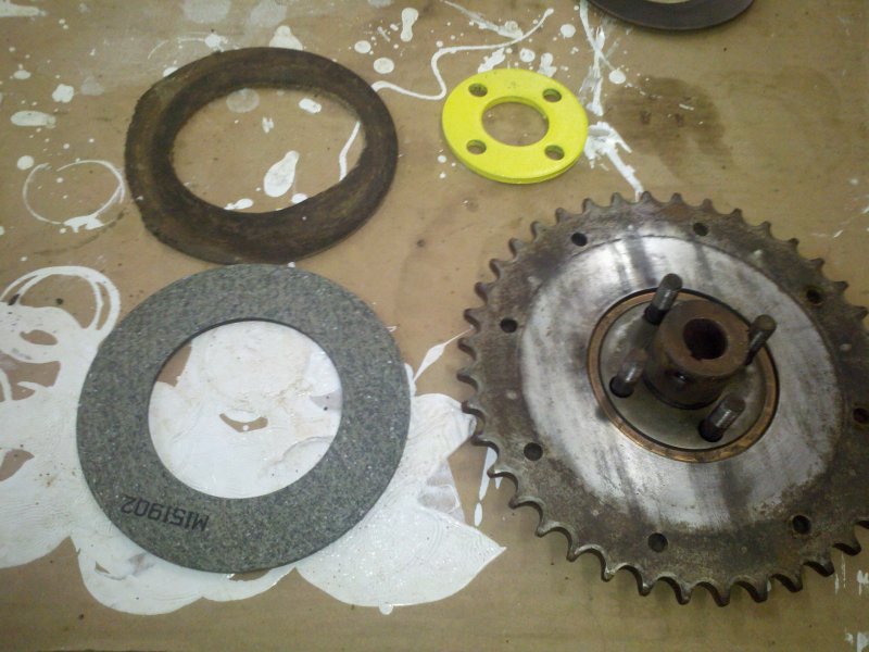
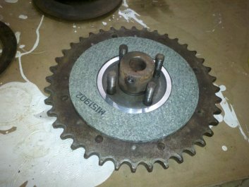
With the
rear clutch disk and sprocket installed, the bronze bushing doesn't
even reach to the top if the sprocket inner hole.
|
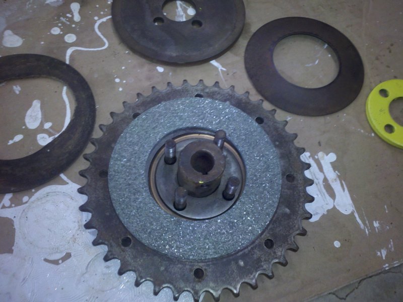
As you can
see, the bronze bushing isn't tall enough to support the outboard
clutch disk. The disk is free to flop around. Very strange.
|
I did some more thinking
on the issue. Another possibility was that if
the bushing was a press fit on the sprocket and evenly centered, there'd be 0.027" of
bushing on either side of the sprocket to support the pair of
disks. I wouldn't think that would be enough bushing to support
the disks, but perhaps I am wrong. Oh well, I've done enough
speculation on what might have happened. At this point, my issue
was
what could I do to fix it?
What I decided to do was
to machine a new bushing that was thick enough to support both clutch
disks and the sprocket. The new question was how thick to make the
bushing.
If I made the thickness equal to the thickness of the two clutch disks
and the sprocket, as soon as the disks wore even a slight amount, the
disks
would slip between the two hubs (#5, #10). That wouldn't do. I decided
on making the bushing thick enough to support the inner clutch disk,
the sprocket and a portion of the way through the outer clutch disk.
That
should
allow for each clutch disk to wear a bit
before I would have trouble with the sprocket slipping due to the
bushing's interference.
To make a new bushing, I
decided to use some aluminum that I had on hand. Bronze/Oilite
would
wear better, but I didn't have any bronze large enough and there really
shouldn't be much wear on the bushing unless I am trying to till a
boulder field - hopefully that's something that I will try to stay away
from.
|
|
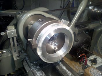
To make the
bushing, I started by boring the center hole to 3.006" and facing the
front side flat.
|
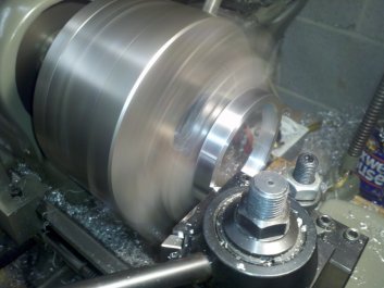
Action shot.
Making the last facing cut on the new aluminum bushing.
|
I
chucked up some 6061 aluminum scrap and bored a hole to 3.006".
The original bushing's inside diameter measured 3.010" and it was a
little loose on the 3" collar (#9 bush), so I reduced the diameter a
bit. I then faced the side of the bushing
flat. I changed chucks to one that could grip the inside diameter
and turned the outside diameter to 3.495". The O.D. of the
original bushing was 3.490". This would be a close
slip-fit on the 3.5" bore of the sprocket and clutch disks. I
then faced the other side until I reduced the thickness of the bushing
to 0.495". This would give me 0.075" of wear on the total
thickness of the two clutch disks before the bushing would interfere
with
clamping action of the slipper clutch. The combined thickness of both
disks and sprocket was
0.570". The sprocket thickness was
0.320" and each clutch disk was 0.125". If I find that the clutch disks
wear quickly and they end up slipping, I can always reduce the
thickness of the bushing to compensate for the wear. Accessing
the clutch pack is a pretty simple job.

|
|
You can see
the difference in thickness between the new aluminum bushing and the
stock bronze one. The rear collar is also shown.
|
If you
enlarge the image, you'll see that there is now just a slight step
between the height of the disk and the new bushing. No more floppy
clutch disk.
|
Once I had the new bushing machined, I compared the parts, then
assembled the clutch pack on the bench. I measured the difference in
height between the bushing and the top face of the outboard clutch
disk. It was very close to my projected 0.075" estimate. Good
deal.
Update: While re-reading
through the original manual that was shipped with the tiller, I came
across a picture that seems to allude to the fact that the bushing was
press fit into the sprocket. The sprocket is shown with the bushing
installed and not as a separate part as it appears in the JD parts
picture. Just enough bushing protrudes from the sprocket to center both
clutch disks. While I didn't see any wear on the outer diameter
of the the original Oilite bushing and the inner bore of the sprocket
didn't appear to be polished from the bushing spinning in the sprocket,
it is still possible that the bushing was a light press fit in the
sprocket. This new information does not change my mind about my
repair. In the worst case scenario I may have to reduce the
thickness of my new bushing some time in the future to make up for
clutch disk wear, but I will take that chance.

|
|
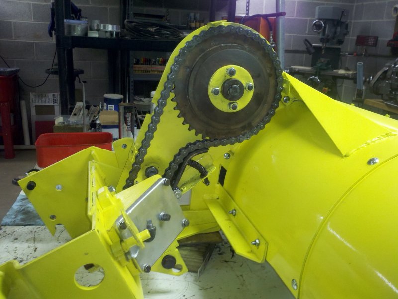
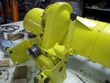
The slipper
clutch is installed along with a new #50 chain and my Delrin faced
tensioner.
|
The saw
blade points to the nut that I needed to loosen in order to get the
chain cover installed.
|
I had purchased some new #50 drive chain in a 10 foot length. I counted
out 59 links and cut the chain. 59 links plus the removable half-link
gave me the requisite 60 links. I added the tiller mount and
bolted on the angle drive. I threaded the new chain around my repaired
and Delrin faced chain tensioner and gave the chain a spin. It
appears that the repaired tensioner is going to work out just fine.
Hopefully
the Delrin doesn't wear too quickly.
Installing the chain cover wasn't as easy as I thought it would
be. The shape of the cover prevents it from being slid on from
above and there isn't enough space to get the narrow (bottom) end of
the cover past the rectangular section of the angle drive and on to the
cylindrical snout that leads to the gear. The manual doesn't
cover this at all. It just says to remove and replace the cover.
I ended up loosening the large nut on the back side of the inner cover
and pushing the back side of the cover away from the direction of the
angle drive. This gave me just enough room to pry the front cover
into place. I cut down some 1/4"-20 screws so that the threaded portion
was about 3/8" and used these to hold the cover in place. There's
a hidden screw between the cover and the tiller body. It was replaced
with a shortened bolt as there is no way to
get a screwdriver between the cover and tiller body, but there's plenty
of room for a wrench.
As I said early on, I broke the bar that sets the width for the tractor
mount section of the tiller. I had initially thought I would bend
up a new one using some 1/2" bar stock. I finally decided that
there was an easier way to go. I shortened the bar enough that I
could add in a 1/2"-13 coupling nut, then cut some new threads on the
end of the bar and added another
piece of threaded rod to the other end of the coupling nut. While
it looks
like a repair, it will work fine and that's what I am after.
|

|
After a bit
of fighting, I was able to get the outboard chain cover in place.
|
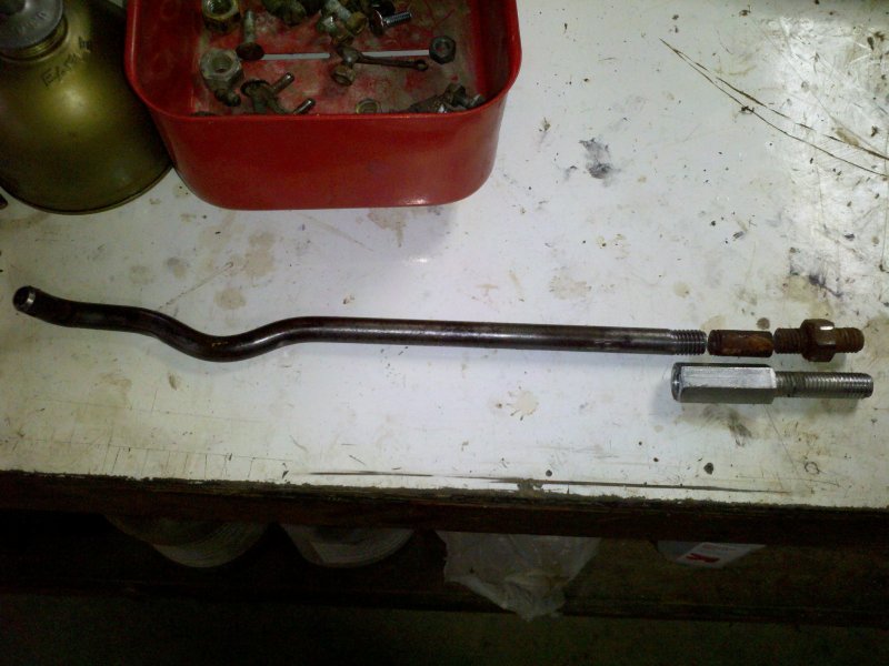
The spreader
bar broke at the beginning of the threads. I cut another section out,
then added threads to the end for the coupling nut.
|
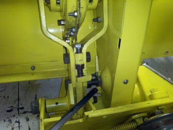
When I tried moving the lever that engages and disengages the idler
pulley,
I found that I couldn't move the lever into the engage detent without
the idler pulley hitting the main drive sheaves. There is a
spring assist to keep tension on the belt and a locking collar to limit
the travel of the idler pulley. Of course the set screw on the
locking collar was frozen and I had to remove the assembly to the bench
to get a better grip on it so that the set screw could be removed. Once
I removed the screw, I cleaned up the shaft, gave it another coat of
paint and reinstalled it. I adjusted it so that the idler stopped a
little further from the main sheaves. I left the nuts that adjust
the spring tension finger tight so I can set the tension once the belts
are installed.

|
|
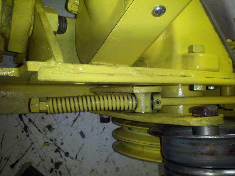
The idler
pulley adjustment collar is set so that the pulley doesn't hit the main
belt sheaves.
|
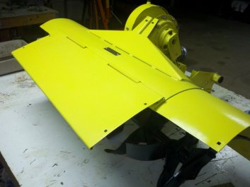
I still need
to fabricate some flaps that will cover the extension tines. I am
thinking of making these from 16 gauge sheet steel.
|
I am pretty much finished with the tiller. At some point, I need
to make a couple flaps for the rear end of the extension housings, but
I may use the tiller without these parts for now. The weather is
turning cold and I am running out of time. I want to till a
sodded area for a much larger garden so it can decompose a bit over the
winter and I still need
to design and fabricate a PTO shaft and double sheave to power the
tiller.
After some reading, I have also decided to run the tiller without the
oval end plates installed. The end plates make it more difficult
for the tiller to dig as deep as it would without using the
plates. It would seem that the purpose of the end plates is to
prevent your plants from getting sucked into the tiller when
cultivating between rows. That won't be an issue for me at this
time. I also may need to remove one or both of the extensions for
tilling this new patch of land. I do plan to plow before I till, but
the soil is pretty heavy with clay and I don't know if the tiller will
be able to handle the hard clay and sod with both extensions in place.
I guess I will find out soon enough.
I still need to make all of the final adjustments on the tiller. I
can't do that until I have it up and running. I set the depth
control bolts to the middle position and will adjust them up or down
depending on how well it tills in this position.
Hopefully I will get this all done in the next couple weeks.

© Fager 9-22-12