Rebuilding
a
Deere
33
Tiller
-
part
2
September 22, 2012
46" / 48" Mower Deck
Just a quick side note about my 46" mowing deck that I couldn't find
online and thought that it might help someone in the same situation.
Problem: The belt from the PTO to the mower deck was jumping off the
deck pulley.
Background: Both the deck (blade) belt and PTO belt were on the tractor
when I bought it and I've been mowing with it for a couple years. When
the PTO belt jumped off the sheave, I reinstalled it and it promptly
jumped off again.
I replaced the belt with a Deere M82718 belt, but also found that
others had used both 4L-90 and A900 belts. The Deere belt was a bit
more expensive, but I was going to be up at the Deere store anyway.
I didn't think to check the blade belt and as soon as I engaged the
deck, the sound of mower deck engaging wasn't what I was used to, so I
shut the 317 down and pulled the deck off. Once I had the deck
belt covers off, I saw that in the two years since I had serviced the
deck a lot of dirt and grass clippings had piled up beside the belt. I
also found that the belt had jumped off the right side pulley and was
hung up below the sheave.
I cleaned all of the dirt and grass, then since I had the deck down,
sharpened the blades. I checked, lubed and readjusted the idler pulley,
then re-threaded the belt; which didn't appear to be in bad shape.
I got it all back together and within a half hour it threw the blade
belt again.
The fix was to replace the blade belt. Apparently the blade belt had
broken a cord or three which was causing the belt to flip off of the
blade sheaves. I learned my lesson. If I should have the problem again,
it will be worth my time to just replace both belts.
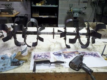
Tiller
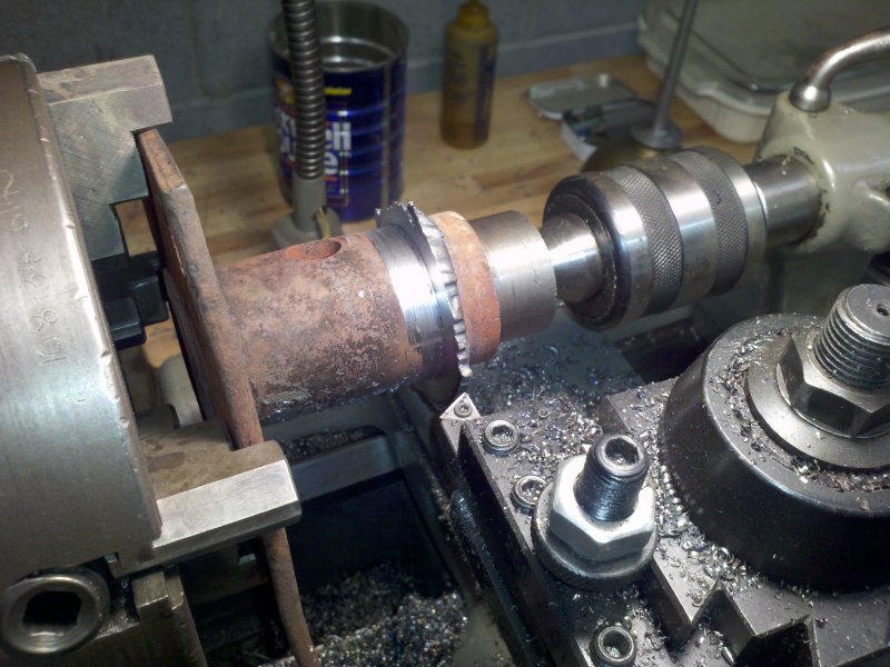
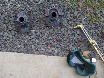
Removing the tiller tines from the carriers took a while. To get
started, I torched off the ends of the tines so I could chuck the
carrier up in my lathe. I used a carbide tool and faced down the welds
to a bit below the blade surface with the lathe. Not precision work by
any stretch of the imagination, but it was good to get a little lathe
time after not using it for a few months.
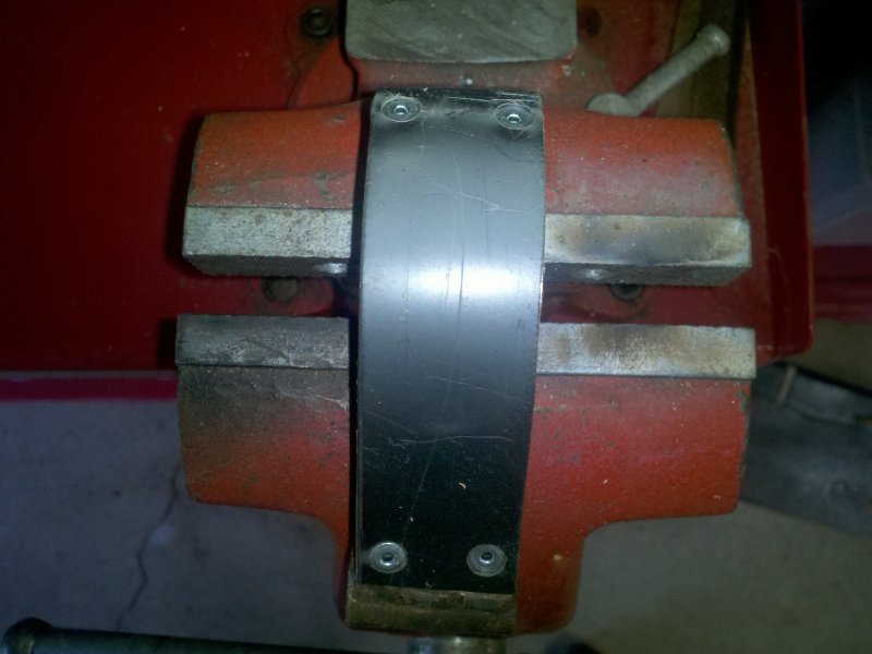
Once I'd faced off the welds, I moved each carrier over to the vise and
cut through the thinnest part of the blade with a hack saw. I did this
on both sides so that the tine was split in two on the carrier. I then
used a cold chisel to wedge open each of the cuts. A few whacks on
either side split the blade in two and allowed me to remove it from the
tube.
Not the quickest or easiest thing to do, but it worked and I ended up
with two tine carrier tubes sans tines.
|
|
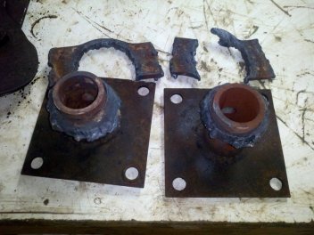
The blade
tips were cut off, then the remaining metal was torched off so that the
extensions would fit in the lathe.
|
Close up
shot. Thankfully I have a torch and lathe. Doing this with a
hacksaw, file and grinder would have taken a while.
|
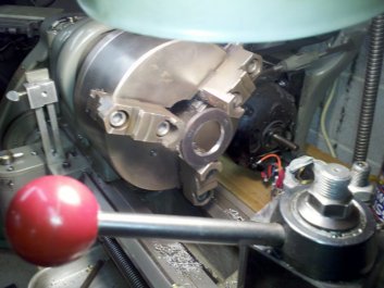
The next day I did the same for the two extensions. One worked
perfectly and the next didn't. It seems that I didn't cut deep enough
into the weld on the lathe. Since I had already used the hack saw to
cut the remainder of the tine in two places, I wasn't happy about
putting the piece back on the lathe. Interrupted cuts and uneven
surfaces don't do well in a light lathe. I could have used a grinder
and spent half the day grinding the tine and welds off, but I decided
on another approach.
|
|
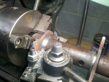
Using the
lathe to cut through the welds that hold the tines to the tine carrier.
|
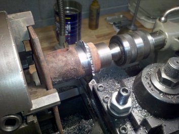
Switching to
a 4-jaw chuck and cutting the tines off of the tine extensions.
|
I mounted the extension in my mill and cut the welds off using a 5/8"
roughing cutter. This took eight set-ups, but since this wasn't
precision work, the set-ups were quick. Once I had cut the welds around
the tube in an octagon, I moved to the grinder to finish removing the
welds around the circumference of the tube. A couple hours work, but
better than doing it all by grinder or breaking a bit on the lathe.
I honed the inside of the carrier tubes with a 2-stone caliper hone and
mounted the 1 1/4" shafts on the lathe and filed off the rust. They now
fit together well. When I reassemble them, I will use some marine grade
anti-seize to see if I can prevent them from rusting together again.
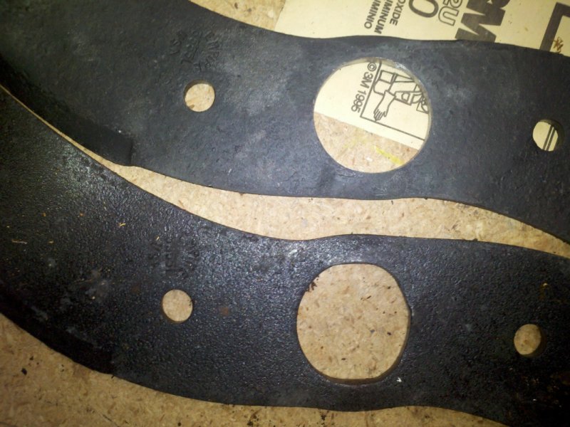
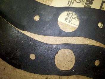
Getting the tines ready for welding was the next job. Unfortunately, I
am not real impressed with the holes that were stamped in the center of
the new tines. They weren't really round and this meant that I needed
to re-size each of the holes in the 14 tines to fit over the 1.375"
carrier shaft. I used a small drum sander mounted in my drill press.
Pretty quick work if you only had one to do, but I had 14. Pretty
shoddy quality control on the part of the manufacturer.
Welding the tines on to the carriers and extensions was the next job.
With the tine holes re-sized to fit over the carriers, I lined each
tine
up with the punch marks I had made before I cut each one off.
Each welded tine appeared to be offset by 45° on the carrier and
then the square plates offset the tines by 90° on both the inner
and outer welded tine. You use a left and right tine on each carrier so
that the sharpened portion faces the same direction. Both carriers are
identical and are just mounted from opposite ends so that the sharpened
area faces the front of the tractor.
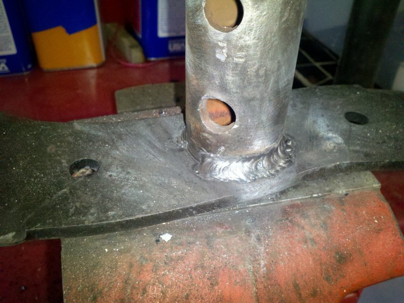
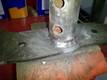
The actual welding was done with my new-to-me Lincoln 225. It's an old
beast of an AC only arc welder, but in remarkably good condition. I
laid a couple practice beads down on the old tines and changed the amp
settings until I got good penetration. I used E6013-1/8" rods and a
setting of 100 amps. I must confess that I am not the most experienced
arc welder, but by the second tine, I was laying pretty good beads. Not
the prettiest of welds, but strong. I did have to grind down a few
welds and re-do them, but I am pretty confident that the welds will
hold.
|
|
Upper tine
has been reamed to 1 3/8".
Lower tine as received. Not a very round hole.
|
I'm starting
to get some nicer looking welds after a bit of practice.
|
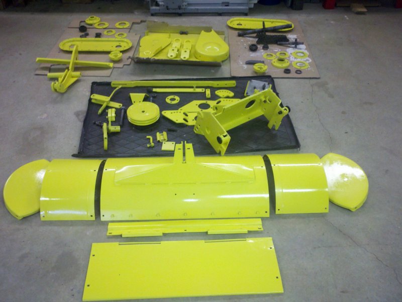
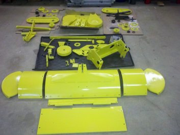
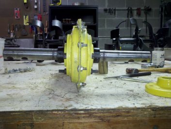
During the
process of getting the old tines off and the new tines welded on, I put
another couple of coats of paint on all of the parts. Aside from
painting the tines, carriers and extensions black, I am pretty much
done with the painting.
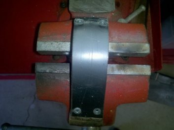
After going through my boxes of plastic scrap, I finally found a piece
of 3/16" thick Delrin that I could use to face the drive chain
tensioner. I
cut it to size and measured the area that the chain would ride on.
There was just enough room to drill and counter-sink some holes so I
could rivet the Delrin to the tensioner. Hopefully the Delrin
will wear well in this capacity. If not, I can always braze on a new
steel face to the tensioner.
|
|
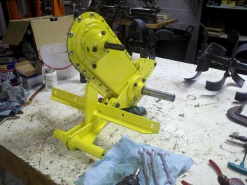
Pretty much
all of the parts now have a coat of Deere yellow.
|
The chain
tensioner gets a facing of Delrin.
|
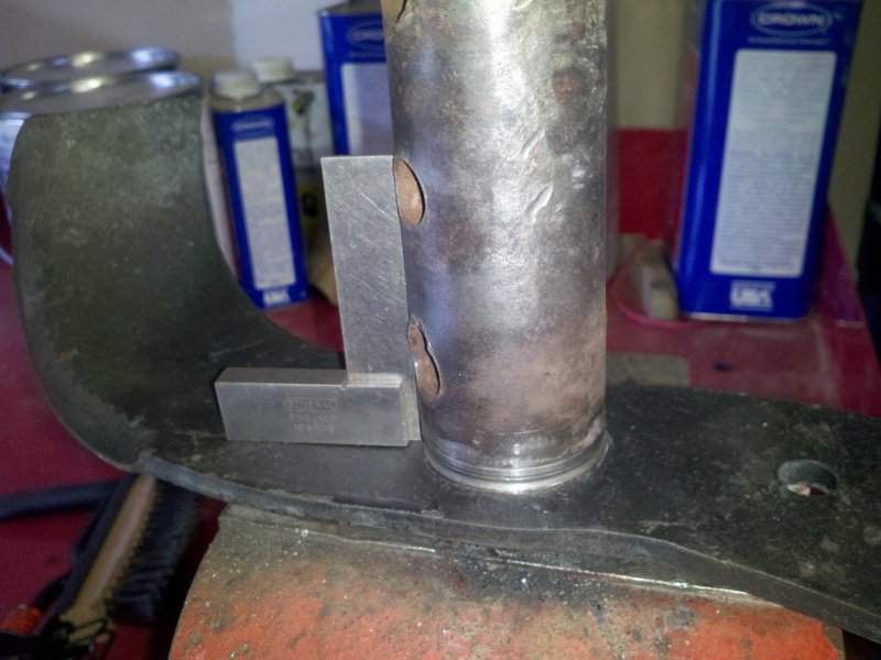
I did some more work on the tines today. This time I worked on
the tine
extensions. I finished reaming all of the holes in the tines that
weren't circular. Then after checking the pictures I had taken before
disassembling the tine assembly and figuring out which way the tines
should face, I welded up the extensions. I used a small L square
to make sure that the tines were square with the extension
carrier. The welds on the extensions came out even better than
the best welds I had made before. I guess I am learning a bit
more. I did a mock assembly of the tines and main chain shaft to
make sure that everything came out correctly. Unfortunately it
didn't. I welded the left carrier outside tine 90° out of
phase - 45° the wrong direction. Darn. I checked that darn
tine twice. I guess I should have checked it a third time. In the
great scheme of things it won't matter as the tines are all staggered
so they'll balance and won't introduce a vibration, but I hate it when
I mess up. Yes, I could grind off the weld and re-do it, but I
won't. The fact that it would look right won't be worth the added
work. Cursing a bit, I then took the tines
outside to give them a coat of black paint.

|
|
Aligning the
carrier to the tine. Yes, it's high on the left, but that was fixed
before welding. Taking pictures while working isn't always easy.
|
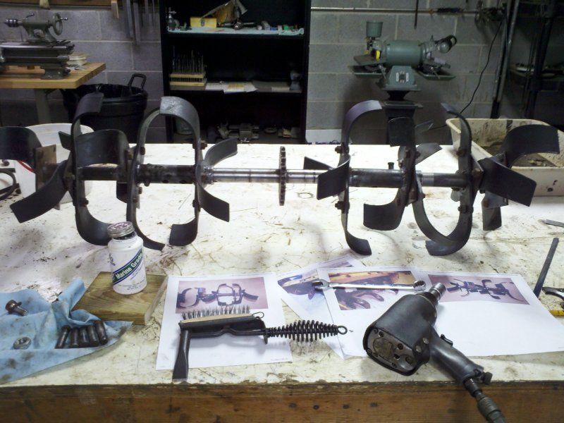
Checking the
alignment of the tines on the bench before they get painted and
assembled. Yes, I use pictures any time I can.
|
Assembling the chain case is pretty straight forward. The top shaft has
the long side facing right. Bottom shaft doesn't seem to matter. I
attached the chain and put the tensioner in place with the bolt loose.
I used a good quality sealant to seal the case halves. Since I
wasn't ready to attach the chain case to the tiller body, I put bolts
and nuts in all positions around the case halves so they would cinch
down evenly. After using an L square to make sure that the lower tine
shaft was perpendicular with the chain case, I tightened the four
carriage bolts on either side of the bearing housings. I then centered
the tine and top shafts and installed the eccentric locking
collars.
Once I had the tine shaft square and true with the case, removed one
bearing housing at a time and installed the thick steel attachment
plates and reinstalled the bearing assembly. Hopefully this would
allow me to keep the tine shaft square with the case. The last thing to
do was to adjust the tensioner.
|
|
With the
chain case sealed, I aligned the tine shaft, then centered the shaft
and installed the eccentric locking collars.
|
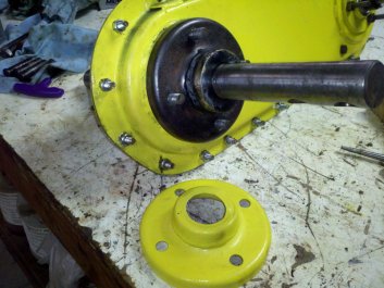
To fix the
bearing guard, I opened the center hole of a large flat washer to 1.39"
as there needs to be a little space around the 1.375" shaft.
|
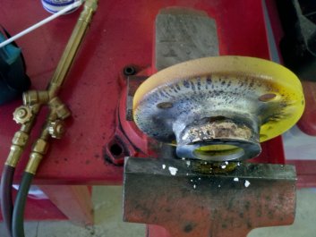
Outboard of the tine shaft bearings, there are a couple stamped sheet
metal covers that help keep crud out of the bearings. One side was in
pretty good shape, but the other had seen better days. It appeared that
roots had wound around the tine shaft an worn through the end of the
cover. There was now a 2" hole where there was only a 1 3/8" hole on
the good cover. I found a large washer in my parts bin and
chucked it up in my lathe to enlarge the center hole to 1.39". I
then brazed the washer on to the end of the cover. It came out
pretty nice and should keep the bearing a little cleaner.
|
|
I aligned
the washer on to the bearing guard and brazed it into place.
|
Before I
gave it a coat of yellow paint, I test fit the bearing guard to check
to make sure that the center hole was centered on the tine shaft.
|
Due to Deere using carriage bolts for holding the bearings on the chain
case,
it's a little tough to get sealant on both sides of the mounting plates
and bearing holders and then get everything aligned before the sealant
sets up or is rubbed off. It's hard to align bolts that move
around. I'm pretty sure that the case won't be totally oil
tight. My original operating manual specifies 30 weight oil in the
chain case, but if I get leaks, I will probably resort to using
motorcycle chain lube. I assume that Deere expected leaks as the
recommended time between oiling the chain is only 8 hours of use.
That sounds like a "total loss" oiling system to me.
|
|
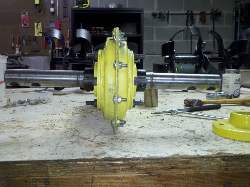
The chain
case is assembled. The case got a bit greasy during the build.
|
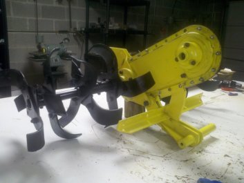
The tine
assemblies are added.
|
I added the tiller tine assemblies, making sure that the shafts and
locating pins were liberally coated in marine anti-seize. Hopefully the
next time this tiller needs to come apart it will be an easier job than
I was treated to. The sheet metal body was installed. The right
side extension was a bit tweaked, but I got it pretty close to being
the correct curvature before I put some paint on it.
Next on the list was to install the upper link arms and height
adjustment screw. The top of the link arms were greased and the
adjustment screw got a coat of anti-seize. The inside drive chain
case half that I repaired the mounting tab on was installed. Next
project will be the slipper clutch.
|
|
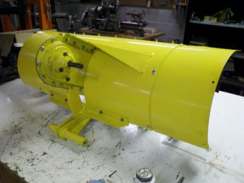
The tiller
body and extensions are added.
It's beginning to look like a tiller again.
|
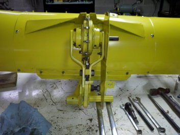
The upper
link arms and height adjusting screw is installed along with the drive
chain case half.
|
More as I get to it.

© Fager 9-22-12