Rebuilding
a
Deere
33
Tiller
-
part
4
October 7, 2012
PTO
I purchased a used hydro fan to use as the end of the belt driven PTO.
I wanted to make sure that if I somehow screwed up building the new PTO
that I'd still be able to use the tractor.
Having bought the fan, I'll probably never need it, but if I didn't buy
it, I probably would. This is my corollary to Murphy's law.
I machined a piece of 2"
round steel to fit the shape of the fan end. I then drilled and tapped
the fan end to accept a 5/16" - 18 allen bolt. This would not only
locate the 2" round on the end of the fan, but also add a little
strength to the assembly after the extra piece was welded to the
end. After trying different amperage settings on the arc welder
on some similarly sized scrap pieces, I found that I couldn't come to a
happy medium in regard to amperage settings. Too low and I could weld
the 1/8" fan blades, but didn't get good penetration on the 2" round.
Too high and I got good penetration on the heavy stock, but burned
through the 1/8". Rather than chance ruining the fan, I decided to
braze it where I have better control of how much and where I focus the
heat. The job doesn't look that pretty, but the weld seems to take as
much punishment as I could easily give it without bending the blades -
and that was without the allen bolt installed. With the bolt installed
it should be able to handle the rotational stress - or at least I hope
so. We'll see how it holds up over time.

|
|
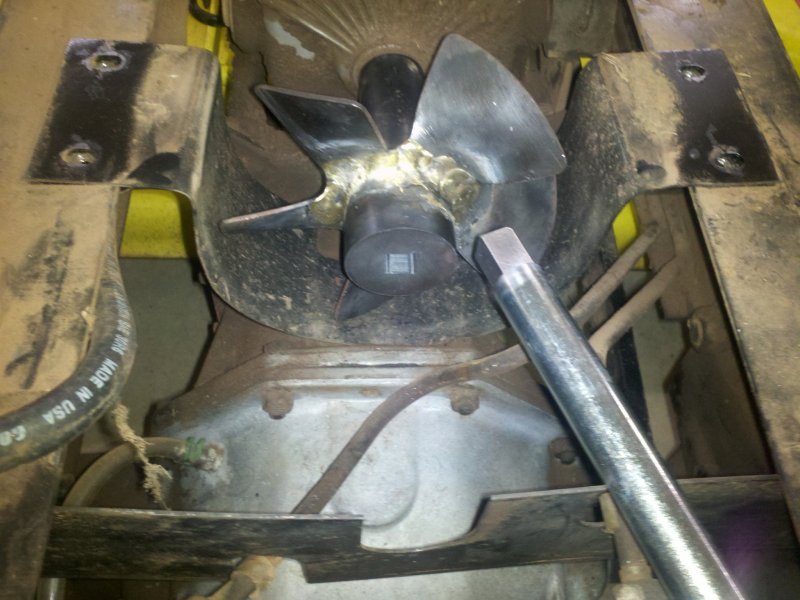
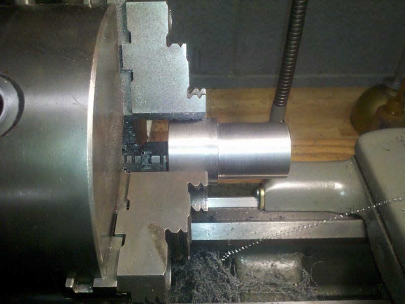
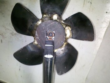
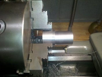
Trying out
the hydro fan with extension welded on.
|
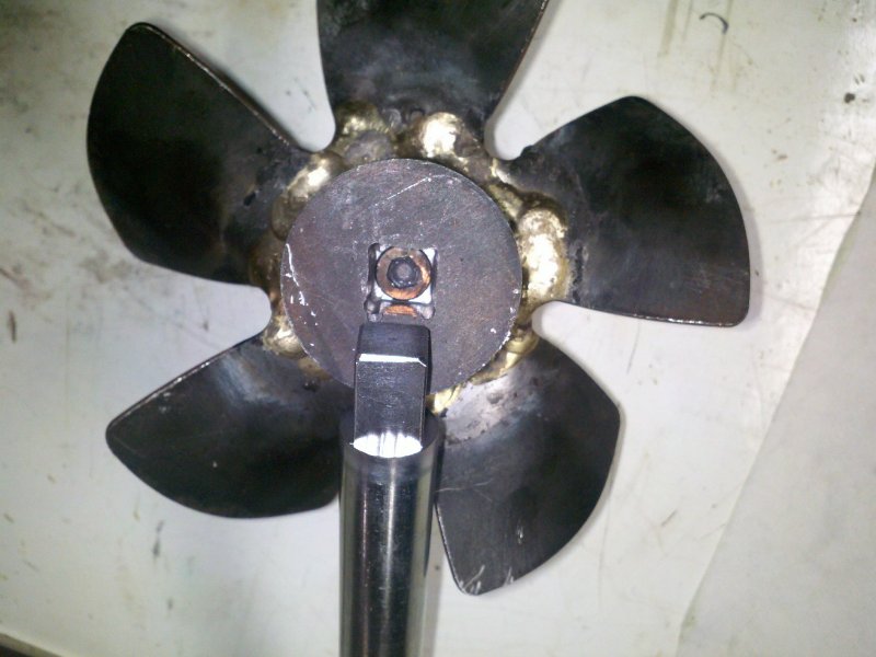
An internal
square was cut in the extension to match the square milled in the 3/4"
bar.
|
The next step was to build the bracket that holds the shaft parallel to
the hydro output shaft/fan. I used some 1/4" sheet steel cut to the
approximate size. I drilled a couple holes to line up with the bolts
that hold the rear hydraulic port bracket. I used an L square to line
up where I thought that the hole for the 3/4" PTO shaft should go and
drilled it to 3/4". This would allow me to see if the alignment between
the bracket and hydro was good before I enlarged the hole for the 1
1/4" ID bearing I would use. While studying pictures of the stock PTOs
I noticed that they all had a collar that was much larger than the
shaft where it passed through the bearing. I assumed that this was done
to be able to use a larger bearing. A bearing with an ID of 1.25"
should be able to take more abuse than one with an ID of 0.75". I
am hoping that my PTO will still be functional in 20 years.

|
|
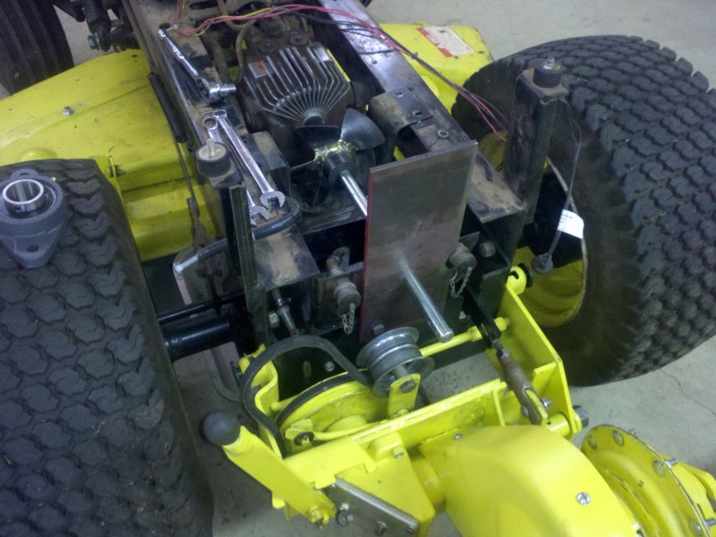
I did a test
fit of the bracket so I could mark where to cut the top of the bracket.
|
I set the
bracket back up on the mill, located the hole and bored the hole out to
1.7" with a fly cutter.
|
With the holes drilled, I mounted up the bracket and checked the
alignment. It wasn't more than about 0.010" high. Pretty good for
"eyeballing" it. I used a 7/8" end mill to move the hole up a bit, then
rechecked the alignment by wrapping the shaft with some lead shim stock
to make up the difference between the 3/4" shaft and 7/8" hole. This
time it checked out to be within a couple thousandths of an inch.
Close enough for this job. With the hole now aligned, I used a fly
cutter to open the hole up to 1.7". This will allow the collar on the
PTO shaft to fit through the bracket and rest on the inboard side of
the bearing.
|
|
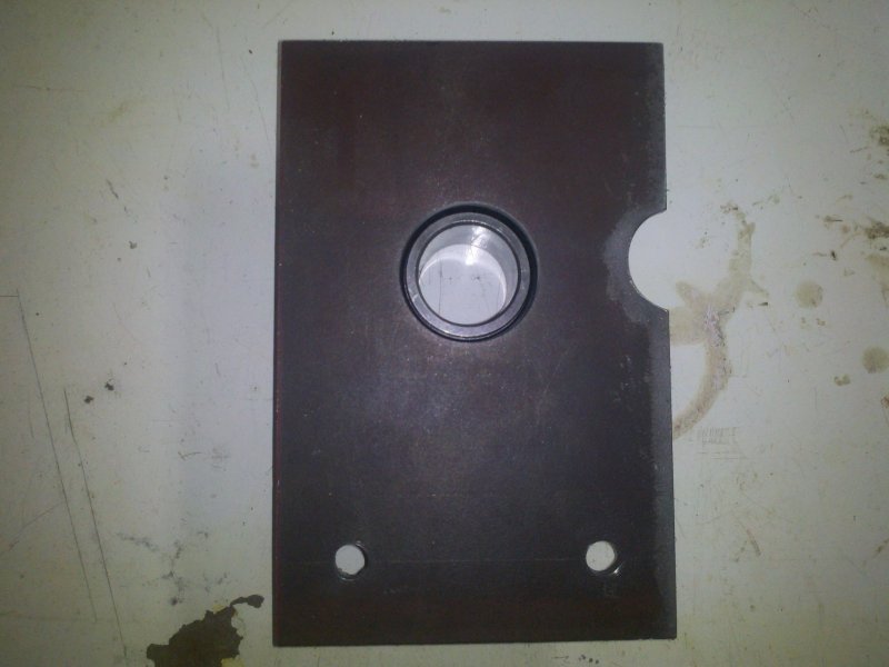
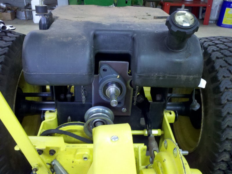
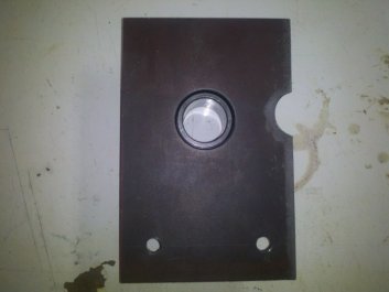
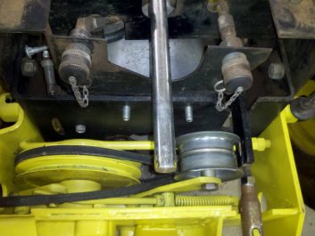
There's now
plenty of room for the PTO shaft and collar that will set the depth of
the shaft in the hydro fan. The cut-out is for the right rear hydraulic
coupler
|
Some drill
rod is chucked up in the lathe to make the collar bushing.
|
Since I was using a bearing with an inside diameter of 1.25 and a 3/4"
shaft, I needed to make a bushing/collar to get the shaft to fit the
bearing. I used some 1 1/2" O2 drill rod and faced one end flat.
I scribed lines for the 1.25" diameter section to be 1.5" long and the
total length of 2.5". I drilled through the bushing, then reamed it to
.75". I was looking for and ended up with a tight sliding fit between
the bushing and shaft. I then turned down the inch and a half section
to 1.24" so that the bushing would have a tight sliding fit in the
bearing.
|

|
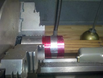
The diameter
of the chucked end is just under 1.5" - diameter is not critical - and
the other end has been turned
to 1.24". This side needs to be close.
|
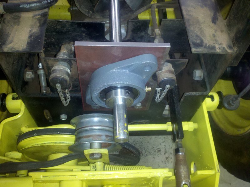
Everything
fits as it should. I still need to add a set screw to the large end of
the collar so it can be locked in place.
|
Before I drilled the holes to mount the bearing to the bracket, I
decided to install
the gas tank and make
sure that I didn't have any clearance issues. It was a good thing
that I did. My bracket was about 3/4" too wide on either side. I marked
the bracket and did some cutting and milling to fix the issue.
With the clearance issues fixed, I moved on to the next issue.

|
|
Houston, we
have a problem. I needed to do a little cutting to gain some clearance
around the bracket
|
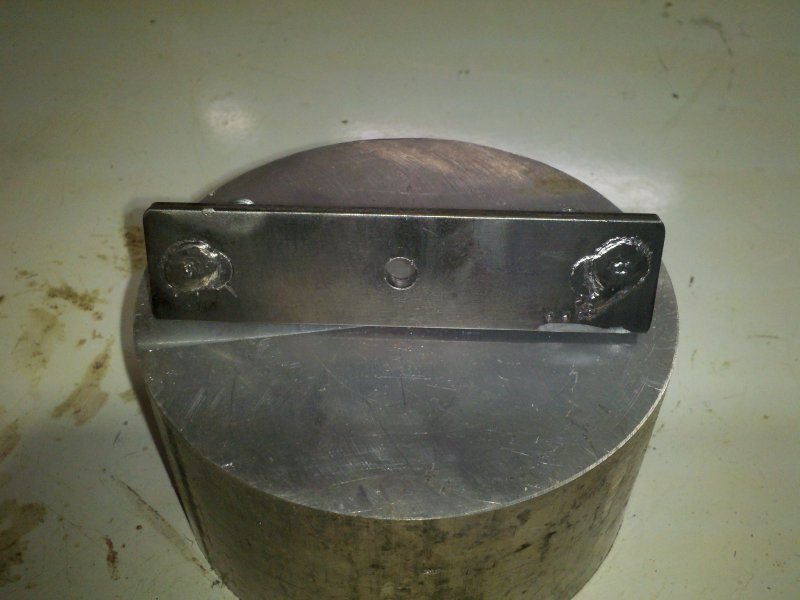
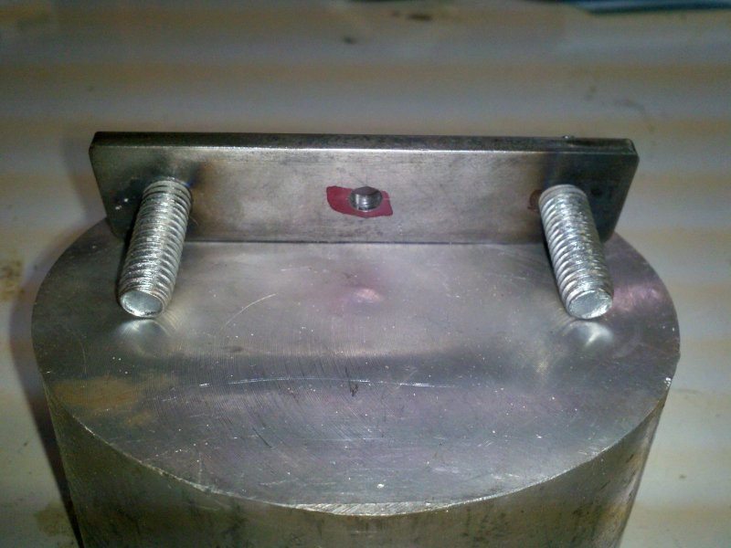
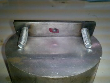
Studs are
tack welded in place on the back of the mounting strap.
|
I wanted to be able to
remove the PTO when it wasn't needed. I had made
the shaft so it could slip in and out, but the bolts that hold the
brackets in place could only be accessed if the fender pan and gas tank
were removed. What I needed were some fixed studs that protruded
rearward so I just needed to remove and replace a couple nuts to mount
the PTO bracket.
I cut a piece of 3/16" sheet steel to four inches and drilled and
tapped a couple
holes for 3/8" - 16 threads. These were drilled three inches apart. I
cut some threaded rod to 1 1/4" lengths and then secured
the studs with a tack weld. I also drilled a 1/4" hole mid-way in the
strap to allow me to secure the strap to the inside of the sheet metal
bracket that holds the rear hydraulic ports.
|
|
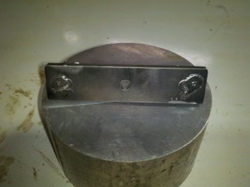
Business
side of the stud bracket.
Two 1.25" studs 3" on center.
|
I used a
sheet metal screw to hold the stud bracket in place. Simple and
effective.
|
I don't know how Deere secured the PTO without requiring you to remove
the fender pan and gas tank on the 317, but this little stud bracket
works great. I've had the PTO bracket on and off a few dozen
times and having to just remove two nuts is a lot easier than having to
use a wrench and socket on a loose nut and bolt.
|
|
|
The stud
bracket is installed.
|
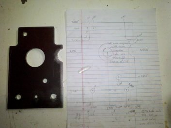
The finished
PTO bracket along with my fabrication notes.
|
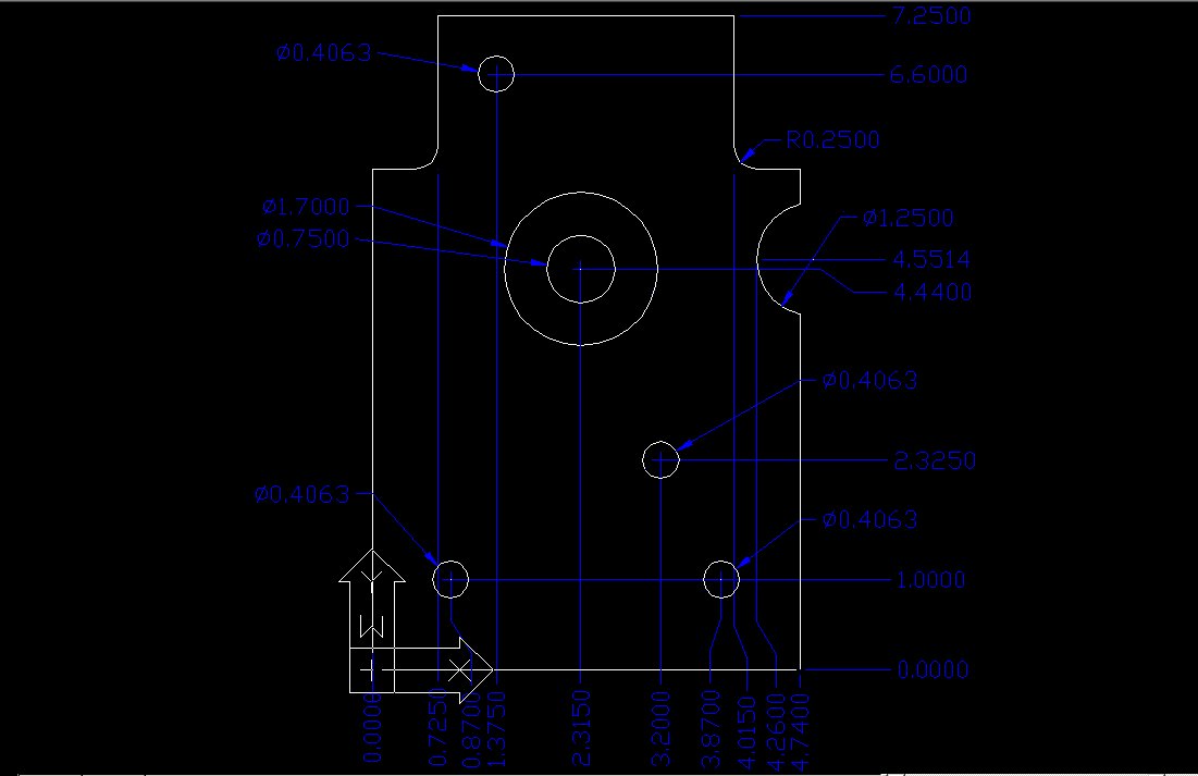
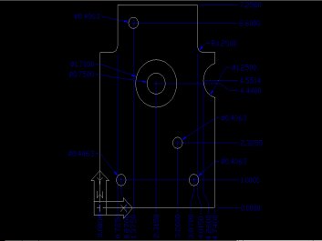
The CAD
drawing in JPG format. Click image for full size or here for the AutoCAD DWG file.
|
With the bracket installed I marked the two holes that would locate the
bearing (UCFL206-20)
on
the
PTO
bracket.
I
drilled
some
13/32"
holes
to
just
clear
the 3/8"
- 16 bolts that would be used to hold the bearing in place. I also
drilled and tapped the collar/bushing for a 1/4" - 20 x 1/2" set screw
to keep the shaft from sliding out of the hydro fan. Once I determined
the correct spot, I milled a small flat on the shaft for the set screw
to press against. Since all I had were 3/4" long set screws, I
used a allen screw for the present time. I have a few bolts and set
screws that need to be purchased before I try using the PTO.

|
|
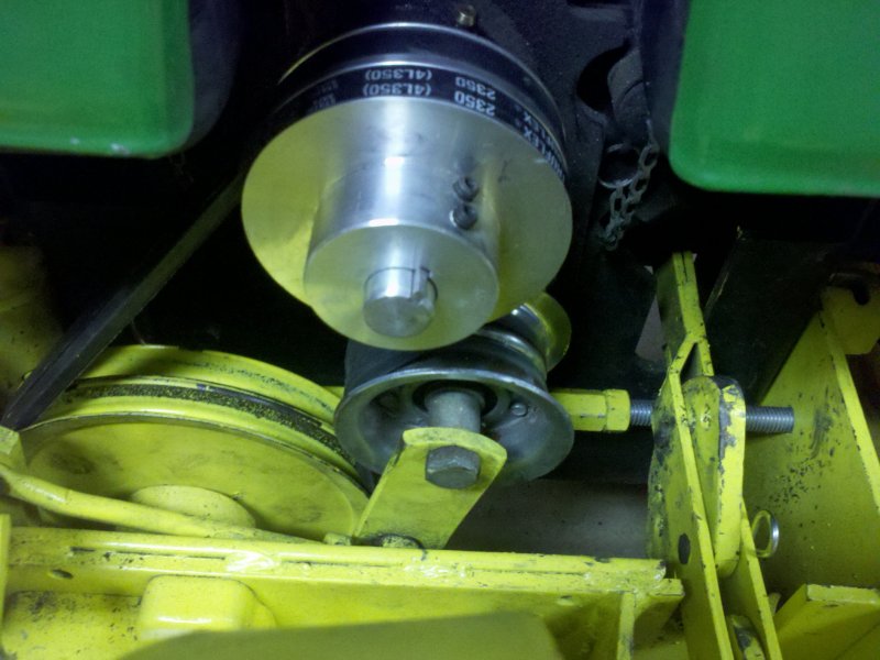
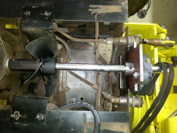
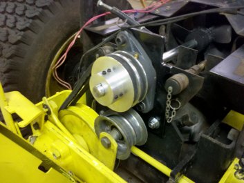
The PTO is
about finished. All that remains is to make a double sheave to
power the tiller.
|
The inner
bushing/collar screw sets the depth of the PTO shaft in the hydro fan.
|
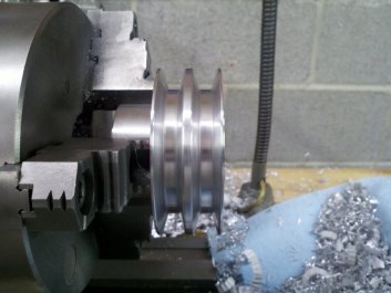
Pulley/Sheave
My Canadian friend, Kevin, supplied me with the dimensions for the
double sheave that powers the tiller. I looked around for a 3 5/8" OD
double pulley for 1/2" belts for a few weeks or so without finding one
that was suitable for this application. Deere lists the price for
this pulley at about $80 and I thought that this was a bit much, so I
decided to make my own. All I needed to do was turn two half inch
grooves to fit the shape of the 1/2" wide x 5/16" deep belts and space
them 3/16" apart. How hard could that be?
As I have never machined a sheave from scratch before, I did a little
research on sheaves and pulleys. It turns out the even though the
v-belt included angle is 40°, when machining a drive pulley, the
angle of the sides of the groove should be machined to a lesser
included angle. This is done so that the wedging action as the
belt is stretched causes more gripping force between the pulley and the
belt. Drive pulleys are generally smaller than driven pulleys and the
machined angle differs depending on their use. It is said that 32°
to 34° for drive pulleys and 36° to 38° for driven pulleys
are the optimum angles for "A" type or 4L belts.
The depth of the groove is also cut deeper than the depth of the belt.
The depth of the groove should be deep enough that even when the belt
is stretched or worn it will not contact the bottom of the
groove. I will machine the depth to about 0.45".
Although aluminum is not the ideal material for a pulley, I chose it
because I have a good assortment of aluminum rounds. That said, I
had an aluminum fan pulley on an old Volkswagen that didn't visibly
wear
for many years and this pulley will only see use a couple times a year.
The closest chunk of aluminum
round I had was 4.5" diameter by 2.25" thick. Almost perfect on the
thickness. The double sheaves and space between them worked out to be
about 1.3" and I wanted somewhere between 3/4" -1" length for the
reduced diameter "snout" that would attach the pulley to the shaft with
a couple of set screws.
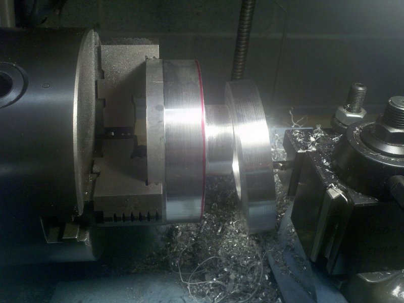
I started by chucking up the aluminum and facing the one side. Now the
width was 2.2". I now needed to turn the diameter of the snout from
4.5" to 2". This would result in a lot of wasted aluminum, so I decided
to cut a ring out of the chunk of round. No telling when a ring with an
OD of 4.5" and an ID of 2+" would be useful for another project. I used
a parting tool to cut a slot in the round and then came in from the
face side to separate the ring from the chunk.
|

|
Using a
parting tool to cut in 2.5". It's a deep cut on a small lathe, so I
advanced the bit slowly.
|
After
grinding a thin bit, I cut in from the side until the two cuts met.
Results: one ring of aluminum saved for a future project.
|
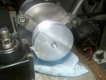
The pulley was drilled for
the 3/4" shaft and then I tried something that I had only read about -
making a key-way slot on a lathe. I used a very sharp parting
tool
and with the lathe off, I used the carriage crank to advance the tool
into the hole. Each
pass was only removed a thousandth or so of material. Very slow going
and there was a fair amount of deflection. This meant that the key-way
was deeper toward the entry side than the rear. I would even out the
depth when I
finished cutting the pulley grooves as I didn't want to un-chuck the
pulley until all of the cuts were made.
|
|
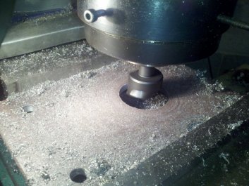
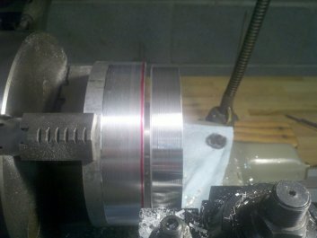
With the
round of aluminum now chucked by the snout, I started reducing the
diameter.
|
I measured
and marked the lines I would use for reference. These match the pulley
on the tiller.
|
I next cut a relief on the rear side of the pulley. This would allow me
to move the pulley a bit closer toward the PTO bearing to set the belt
alignment. In hind-sight, a bearing with a slightly shorter inner race
would have not required the relief to be cut in the pulley. On the plus
side, the closer the pulley is to the bearing, the less leverage force
that will be exerted on it.
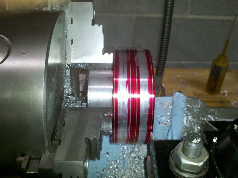
To cut the groves, I measured and marked the lines I would cut to. I
ground a bit with each side angled to 16°. I started in the center
of each area I had marked for the groove and by advancing the bit 10
thousandths for each pass, I cut the grooves. I finished the job with
some crocus cloth to round over the corners of each groove so that the
belt would not get cut.

|
|
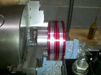
Using a bit
ground to 16° on each side, I started cutting the grooves.
|
First groove
done and starting on the second.
|
When I was done with the grooves, I removed the pulley from the lathe
and used a file to even out the key-way.
The next step was to cut a key-way in the PTO shaft. This was done with
an end mill on the milling machine. I then cut a key from some mild
steel stock and spent the rest of the evening filing and adjusting
until the pulley, key and shaft all fit together nicely.
|
|
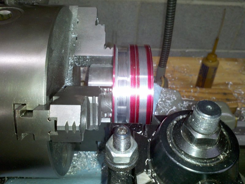
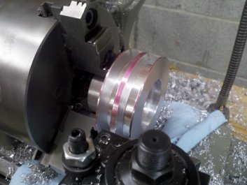
The grooves
have been cut and the edges have been smoothed with some crocus cloth.
|
Test fitting
the pulley on the PTO shaft. Everything aligns as it should. Looks like
I'll need some new belts as these don't seem to be a matched pair.
|
I had a couple choices for holding the pulley on the shaft. I could
drill and tap the end of the shaft for bolt that would run parallel to
the shaft or use set screws at a right angle to the shaft. Due to not
having a shoulder on the shaft to clamp to, I decided on using set
screws. I drilled and tapped the pulley for two 1/4"-20 x 3/4" set
screws over the top of the key and two more offset 90°.
Probably a bit of over-kill, but I'm betting that the pulley doesn't
come loose from the shaft.
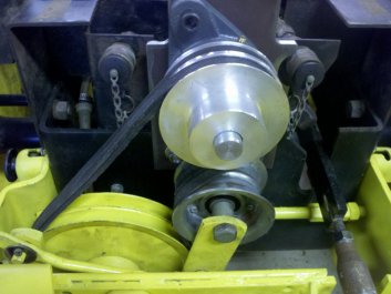
Last thing on the PTO agenda was to give the PTO bracket a coat of
gloss black paint. That done, I assembled the PTO and bolted it
in place. I have to say that installing this PTO is as easy as
installing any other of the Deere accessories I have.
|
|
Two pair of
set screws. Two over the key and two at ninety degrees. Over-kill, but
what the heck.
|
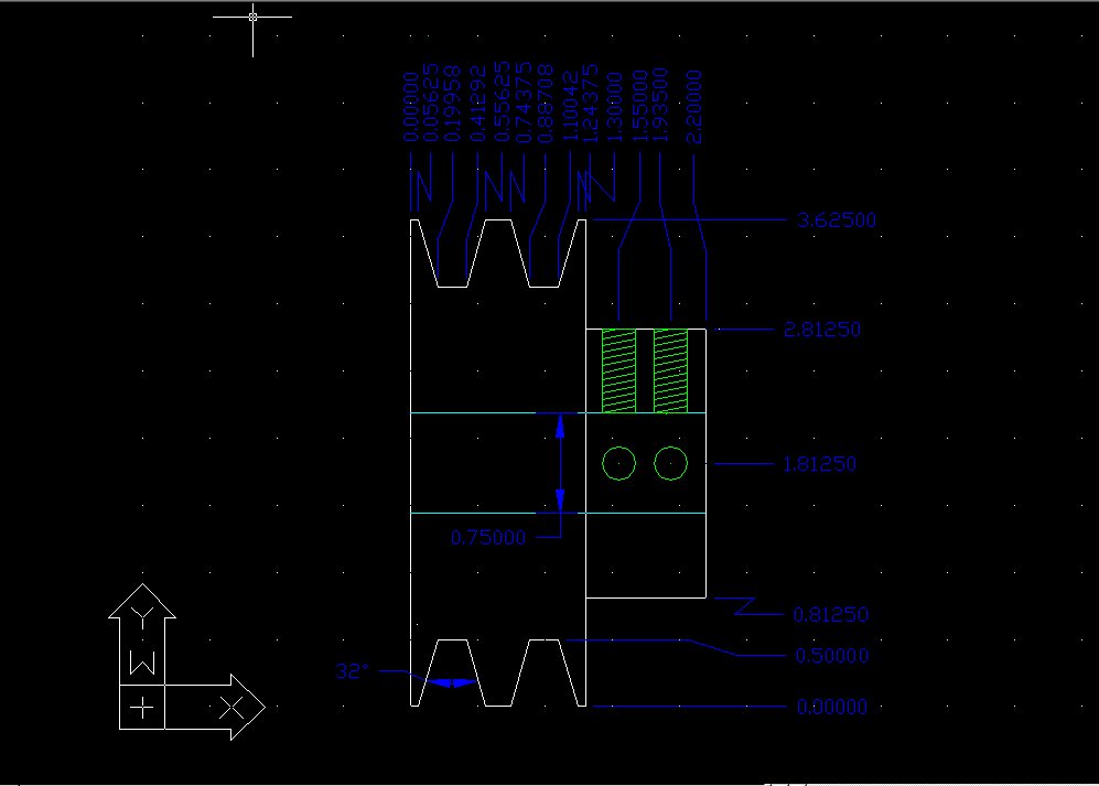
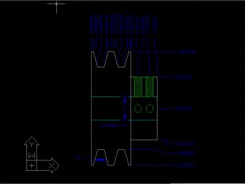
Drawing for
PTO double sheave. Click image for larger view or here for DWG file.
|
October 12, 2012
I put the gas tank back on tonight and fired up the 317. With the idler
pulley disengaged, the tiller tines turn slowly. Unfortunately this is
normal for an idler pulley clutch. You could probably
stop them from turning by putting the tines into the earth, but I sure
wouldn't want to try and stop them with my hands. I pulled on the
hydraulic lever to raise the tiller off the blocks I had it positioned
on and engaged the idler. It's alive!
The tiller is really quiet.
Just the whirring of the chains and tines. Sounds really good. The rear
belt was flapping as it's a bit longer than the front one. Both belts
are in pretty sorry shape. I have to get some new belts ordered,
but hopefully the old ones will last long enough to try the tiller out
tomorrow. I'd like to know that I assembled everything correctly and
that I don't need to strip it down to fix some problem or another.
The tiller
came with a link rod that was meant for a 140. It appears that
Deere added a transmission mount on the 317 (300 series) that
interferes with the straight link
that the 140 used. Kind of strange that the mount wasn't designed so
that the same link could be used as it is very close to fitting without
interference. The link rod
that I built for my sleeve hitch will work to raise and lower the
tiller, but it lacks the depth
adjustment cam for locking the tiller into the desired position.
It does appear that one could notch the 140 link rod and make
it clear the trans mount, but you'd need to strengthen the area of the
notch. I
will have to give this a little more thought. Tomorrow I'll give
the tiller a road test and see how it performs.
October 13, 2012
I decided not to try and run the tiller using the link rod that I use
for my sleeve hitch. If I used it, there is no way to lock the tiller
all of the way up in the transport position. The cylinder that
controls the rock shaft does leak down a bit and I didn't want to
chance the tiller hitting the ground as I drove out to the area I am
going to till. My choices now were to either notch the 140 link rod or
fabricate a new one. I guess I could also wait for a 300 series link
rod to show up somewhere, but the chances that I'd find one before the
weather gets too cold are probably slim.
I decided that I would cut a notch out of the straight 140 link arm so
that would clear the transmission mount. This would reduce the amount
of metal in the rod by half, but seeing as there are two 3/16" pieces
of steel strap welded together, it should be strong enough to test the
tiller. Once I test the tiller operation, I will weld in a section to
strengthen the rod and still clear the transmission mount.
With the modified link rod in place, I could now use the depth
adjusting cam. I raised the tiller and locked the cam into the
transport position and rode out to the new garden area. I readjusted
the cam and set the depth for about 2 inches. I fired the 317 back up
and engaged the tiller. As I lowered the tiller into the soil, it
pushed the tractor forward a couple inches while chewing through the
short grass, weeds and soil. I slowly drove forward about 20 yards and
stopped to examine my work. The ground was nicely shredded with the
bits of sod and roots sitting on top of the soil. I didn't hear any bad
noises coming from the tiller and all of the tines were where they had
been welded. So far, so good. Another couple passes and I
checked the tiller over again. Still good. I ended up tilling a section
about 70 feet by 25 feet before one of the belts flipped off. I was
expecting this but at least I was able to test out the tiller and it
passed with flying colors.
|
|
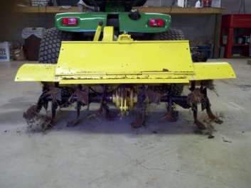
Back in the
shop and the tiller has broken some ground - as well as shredded some
belts.
|
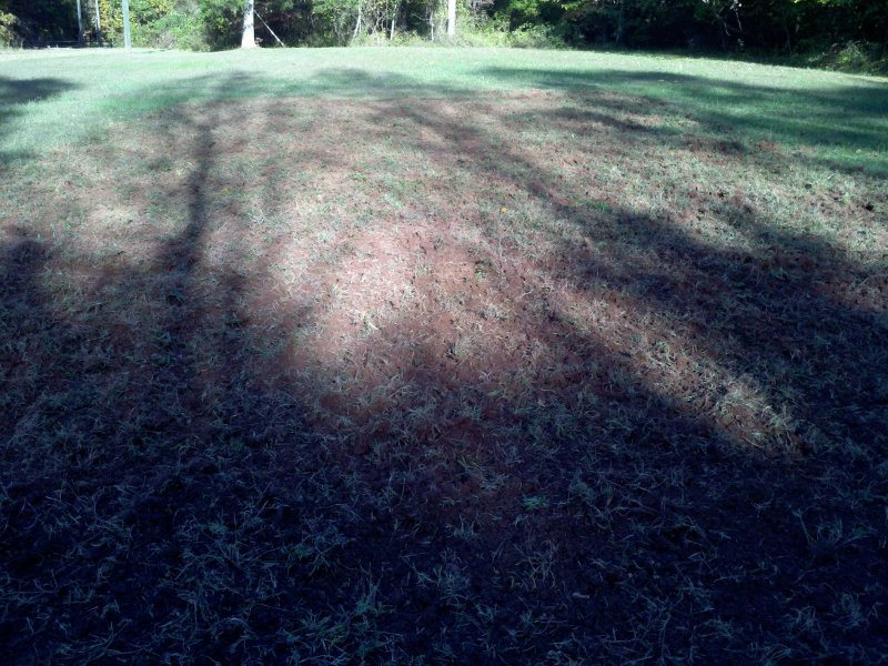
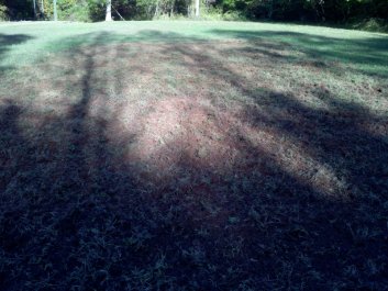
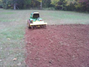
Long shadows
show it's late in the day, but we now have a part of the new garden
tilled.
|
In the tiller manual, I had read that when using both extensions one
should not try to till full depth in one pass. As I learn what the
tiller is capable of, I will error on the side of caution and try not
to stress it too much. I am trying to till fairly hard packed
clay sod that has not been broken in at least 20 years (and maybe
never) so being cautious is probably the best way to approach this job.
As I said, I need to order a pair of belts for the tiller.
Depending on the PTO style, Deere lists two: AM32172 and AM32636.
From what I can tell, the former is for the earliest solid-shaft PTOs
and the latter for the rest. The AM32172 has a length of 35.4 and the
AM32636 has a length of 35.76. In the belt cross-references I looked
at, they both supersede to a 4L-350 belt. Seeing as how my PTO is
shop made, I'm not sure that three and a half tenths of an inch are
going to matter. In the past, I have purchased all of my Deere belts
from Deere. However, I can get two 4L-350 belts for $11 delivered in a
day from McMaster.com and Deere wants $40. I'm all for supporting my
local Deere dealer, but not this time. We'll see how it goes.
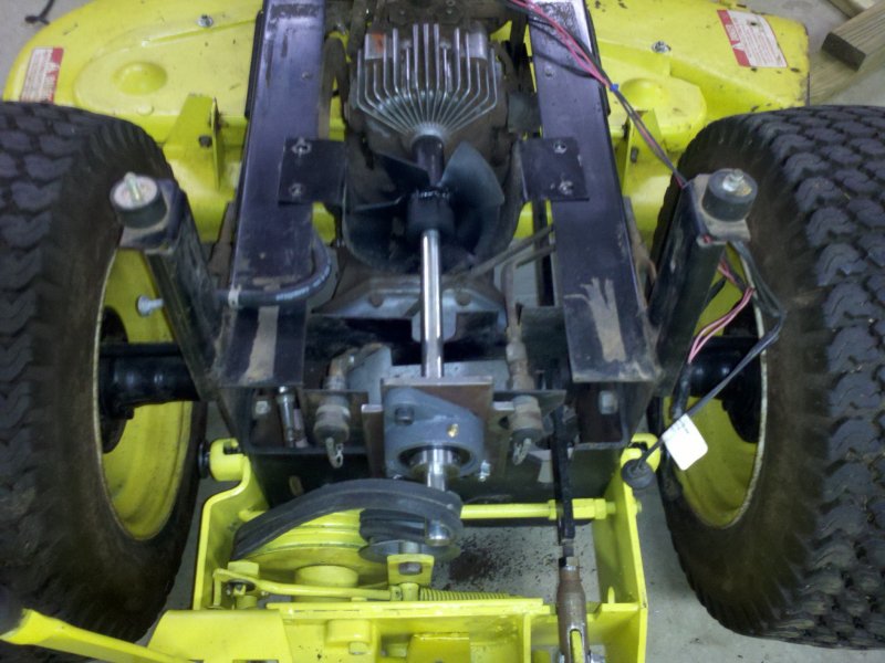
|
|
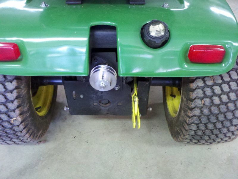
I think that
the PTO pulley looks pretty good peeking out from the fender pan.
|
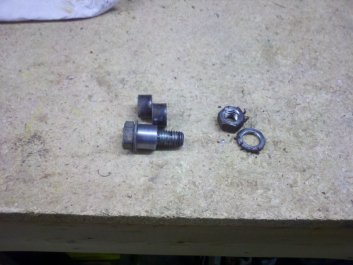
New
attachment stud bushing on the bolt and the old ones above it.
|
October 18, 2012
The belts arrived yesterday. As you'd deduce from the number, they were
35". So they're between a half or three quarters of an inch shorter
than either of the Deere belts. They were a bit tough to get over the
pulley and I ended up using the old mechanic's trick of using the
starter to bump them on. However before I could put them on I had to
deal with something I had forgotten to do.
The attachment studs that hold the bottom tiller mount to the bracket
were too short. The existing studs had a 0.320" wide bushing. This fit
the sleeve hitch perfectly, but the tiller mount was a little more than
1/2" wide. To test the tiller, I had just loosened the studs, but
there's no way I would run it like that for more than a test. The
stud bushings are .75" OD and .5" ID. I used some 1" drill rod to
make the new bushings on the lathe. Outside diameter was 0.75"
with an 0.5" hole and 0.550" in length. I
re-used the original bolts. I used a zip tie to attach the old bushings
to the sleeve hitch so I wouldn't lose them.
|

|
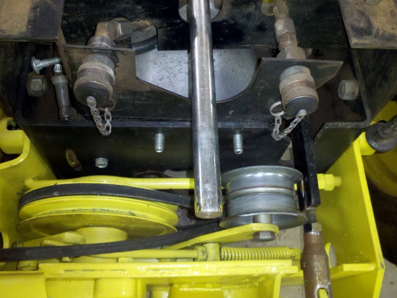
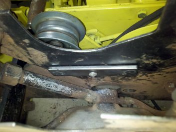
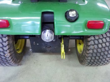
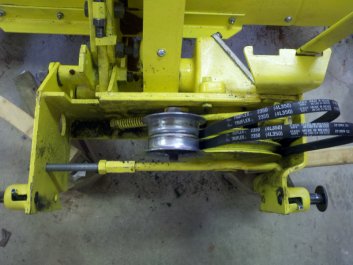
The new
belts are in a lot better shape than the old ones. You can see the
modified position of the coupler on the spreader bar.
|
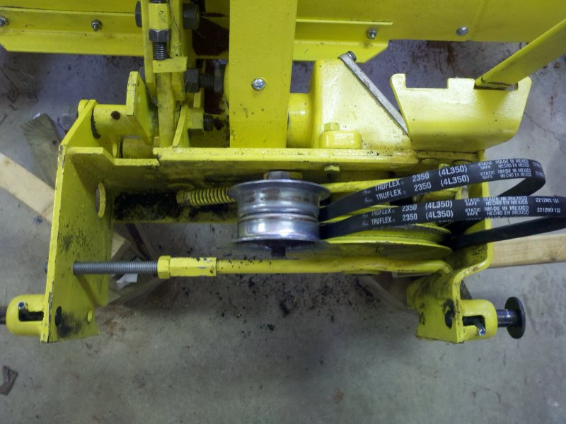
It was a bit
of a fight to get the new belts over the pulley but they work great.
The tension is set and the two belts seem to be exactly the same size.
|
In my test I had also found that the coupling nut I used to fix the
spreader bar was in exactly the wrong spot. It rubbed against the depth
adjuster cam and made setting the depth tough. I cut the spreader bar a
bit shorter and re-threaded it so that the coupler was moved to the
left a couple inches. By this time it was getting late. No trying
out the new belts tonight.
Late this afternoon I finally got a chance to run the tiller with
everything fixed. I'm impressed with how well it works. I
set the depth to about 4 inches and tilled the area I had tilled the
other day. I then went back over it at full depth. It did a real nice
job of cutting up the sod and mixing it in with the soil.
Tomorrow I will work some compost into the soil and let it be until
spring.
|
|
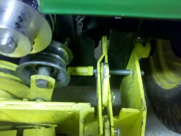
The depth
adjustment cam now has plenty of clearance from the spreader bar.
|
Blurry
picture, but the tiller has done a great job of breaking up the sod and
mixing it into the soil.
|
This tiller has not been the quickest or easiest repair/restoration job
I have done, but seeing the tiller produce fluffy soil from the hard
packed sod has made the journey well worth the time and money spent. As
I hope will always be the case, I learned a few new things and got to
use some tools. I can't ask for much more than that.
If you have questions or comments, drop me an email.

© Fager 10-07-12