HOME
What's New


Workshop Stuff

Workshop

Moving the mill

Spindle Noises

ShumaTech Digital Readout

ShumaTech DRO Continued

ShumaTech
DRO-350 Repairs


South Bend 9" Lathe

South Bend 405 Lathe Bench

Grizzly Mill Revisited

Surface Grinder Rebuild

Surface Grinder Continued

Grinder April 6, 2008

Grinder April 20, 2008

Grinder August, 2008

Grinder September, 2008

Grinder November, 2008

Grizzly G3103 Mill
Rebuild

Grizzly G3103 Mill
Rebuild - Part 2

Moving the Shop

Moving the Shop 2

Bringing Home a Sheldon 12" Shaper

Sheldon 12" Shaper 2

Sheldon 12" Shaper 3

Sheldon 12" Shaper 4

Sheldon 12" Shaper 5

Sheldon 12" Shaper 6

Sheldon 12" Shaper 7

Sheldon 12" Shaper 8

Sheldon 12" Shaper 9

Way Alignment Tool


Email Jim


 workshop.gif
March 8, 2008
DoAll D624-8 Surface Grinder

DoAll D624-8
My new/old tool: a 1967 DoAll D624-8 Surface Grinder.
About ready for its new home.
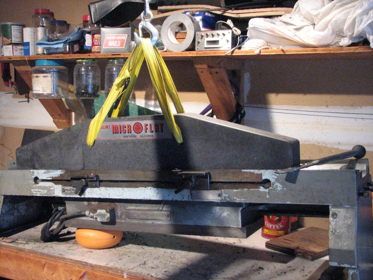
  I need to make some parts really flat with a nice finish, so I'd been looking for a surface grinder for a while.  Call it a couple months of thinking about it and many more months of actively looking.  In the beginning months, I did a lot of reading and studying to try and decide what style, make and features would fit my planned usage the best.  I really wanted the impossible, but don't we all.  I wanted a grinder that could handle 18" or longer pieces and grind them to dead flat with a great finish.  I also wanted one with hand feed to keep it simple and one that was light enough that I could move it into the basement.  To top it all off, I didn't have a lot of money to spend.  Call it $3500 tops including a way to power it off of my residential 110/220 single phase home wiring.  One other requirement and possibly the one that gave me the most trouble was that I needed it close enough that I could pick it up so I didn't blow most of my budget on shipping.

I saw a few in the beginning that might have worked out well but I didn't have a way to get them as the trailer I was going to use didn't have any license plates on it.  This took a while to rectify and while I was waiting, I had to pass on a few that might have been good deals.  However, as often happens, during the time I was waiting, I was learning more and more about surface grinders and those that I might have considered in the beginning turned out to be different from what I looked at later.

Among the changes I made to my wish list, I decided that I would look for a machine with the X axis (at least) that was powered.  Once I read a couple of bulletin board comments that turning the cranks of a surface grinder got old real quickly, I immediately thought of my mill and turning the wheel of the Y axis.  Yes, turning cranks gets real old, real fast.

The next wake-up call was on the Friday after Christmas when I set off to Baltimore to take a look at a couple machines I had seen on Ebay that were being offered by two used machinery dealers.  The first shop I visited was in the old industrial section of the city.  I spoke to the salesman for a couple minutes and told him I wanted to see the DoAll G1 that came out of a Navy facility and was listed on Ebay.  Rightly or wrongly, I was thinking that there was a good possibility that it would be in nice shape.  The machine (paint) looked good in the Ebay ad.

Their warehouse was stacked full of machinery of all descriptions and the G1 must have been there a while, as it was blocked in by at least 4 machines on all sides of it.  The ad had read that it was in good shape, but didn't come with a chuck or coolant, however when it was plugged in, the spindle ran, but the hydraulic pump motor wouldn't kick in.  The shop mechanic came over to take a look as I also gave the machine a "once-over."  I found the reason for the nice looking picture.  It had been recently repainted and they did a fine job of matching the paint on the pallet to the paint on the grinder. Even if they would have gotten the hydraulics working that day, I would have passed on the purchase for the simple reason that the machine had been repainted.  I don't think that repainting a non-running machine is a very good way of prepping a machine for sale.

I looked at the rest of the surface grinders in my price range and we ended up back by the G1.  The salesman disappeared and I was left with the mechanic.  We got to talking and I asked him what he thought about the machines we'd looked at.  He said that the machine to get was the Gallmeyer number 35.  This 8 X 24 sized machine did look pretty nice.  It had not been recently repainted and the sections of the flat and inverted V ways that I could hit with my flashlight showed some remaining scraping marks.  It wasn't a huge machine, but it looked heavy.  The access door on the rear of the Y axis casting (spindle elevation) was the darnedest thing.  It definitely came from the era when cast iron was cheap.  The door was about two and a half feet tall and a foot and a half wide.  It was about four inches deep and shaped like a roasting pan for cooking Thanksgiving turkey, except that instead of stamped sheet metal, the pan was made of half inch thick cast iron.  One hundred fifty pounds or more, easily.  The electrical box on the left side of the machine was also cast iron and massive.  The ten horse,three phase motor turned three V belts, which then turned the spindle. This was definitely an industrial strength machine.

DoAll D624-8
The table gets lifted off of the grinder.
Just my luck that it begins to sprinkle, then pour rain.

Aside from the weight, I thought it was pretty nice, but I was still hoping to move this into the basement and there was no way I could move a machine with an estimated weight of 4500 pounds - or so I thought at the time.  The maintenance mechanic seemed to think that this was one great buy at $2000.  He said that he had worked on this model for many years and was much impressed by the quality of the work produced by it. I passed on both machines for the time being and headed to my next location, but was quite surprised when I next checked Ebay and found this grinder listed as in only "fair" condition.  Either the lister was confused or the mechanic wasn't telling the whole story.  I guess I'll never know.  I was beginning to realize that in my price range, buying from a machinery dealer might not give me the best bang for my buck.

By the end of my day on my long drive home, I began to reassess my wish list.  I was now considering a hydraulic machine and installing it in the garage, rather than the basement.  I kept watching Ebay,various bulletin boards, and Craigslist for grinders.  On January 11th I did a Google search for surface grinders on Craigslist.  I got a hit in Richmond, VA for a DoAll.The ad was about a week old.  I emailed the guy and was told that the grinder was still available.  I got his number and called.  The grinder came from a manufacturing plant that had used it years ago, but their products changed and it hadn't gotten a lot of recent use. This manufacturer was closing its doors and moving off-shore.  (A lot of that going around, isn't there?)  The guy I was talking to helped to pack up the facility and was given the surface grinder as partial payment for services rendered.  I asked what he thought it weighed (he said about 2000 pounds) and if he had a way to load it on the trailer and was assured that he had a industrial pneumatic chain hoist on a huge gantry that would lift it from his trailer to mine.  With that in mind I decided it was worth a look.  I spent the rest of the night reading everything I could find about the1967 DoAll D624-8 grinder.  I did happen to come across the weight.  The weight was closer to 3500 pounds.  How the heck was I going to move this?

Saturday morning.  My wife, Susie, and I loaded up the truck with tools, hooked up the trailer and headed South. About 5 hours later we arrived to find the surface grinder in the back of a small heavy duty dump trailer parked under a massive 12" thick, 20 foot tall I-beam gantry.  The industrial strength hoist he mentioned didn't appear quite so massive as I thought it should.

I spent some time looking the machine over.  As I couldn't see it under power, I looked it over the best I could.  With a mechanic's inspection mirror and flashlight, I checked the ways.  There
was scraping visible on the ends and it showed some amount of polishing toward the center. I was again surprised at the depth of the scraping marks.  All of the surface grinders I had looked at had fairly deep scraping marks.  Whether or not I had only seen machines that had been less than professionally rescraped at some point in their lives, I don't know, but none of the surface grinders I had looked at had the smooth surface found on the bed and saddle of a lathe.  Being a novice to surface grinders is frustrating as I don't know what these machines look like when new.  There was.plenty of old lubrication evident, but it did appear that the grinder had not been run at all lately.  There was a discolored line where the channel cut in the ways met with the flat area of the opposite ways.  This is the channel where the way-lube runs.  This machine has a constant lubrication pump and its reservoir was about half full.  The reservoir comes with a float that turns on a light when it starts to run low on lube and shuts down hydraulic power before the lube runs out.  This is a real good feature and as long as it remained operable, the ways would have always had lubrication.  It does not appear to be disconnected, but I'll learn more when I power it up.

I cranked the table from end to end.  It felt very smooth, but there wasn't much to be learned from the exercise except that the rack and pinion seemed to mesh properly.  If the machine had been rescraped, this mesh could become an issue.  The rack to pinion mesh becomes tighter with the removal of stock from the table ways. I turned my attention to the spindle.  With a hand on the spindle housing I spun the spindle.  No discernible rumble that would indicate that the spindle bearings were bad.  This wasn't conclusive as the belt was still attached and I couldn't get a lot of spindle speed, but if they were horrible, I should have been able to tell, just as one can tell bad vehicle wheel bearings by spinning the wheel and feeling the axle housing.

The inside of the electrical box looked good and clean. No jumped wires, no funky repairs.  There was a lot of some type of old lubrication around the machine.  However there were no pools or puddles below any of the hydraulic cylinders or lines.  The automatic lubrication feature pumps lube on to the ways and the excess drips down to a collection pan at the rear of the machine.  I'm sure that over time this lube ends up everywhere, so that could explain the light coat of lubrication I saw.  I would have been more concerned if the machine was dry.  The paint on the machine wasn't very nice at all, but that was to be expected.  It had been repainted at some point in its life, but that was a long time ago and coolant had done a number on the paint around the table and saddle. Coolant.  Yes, it has the optional cool grind coolant system.  This includes a better filter on the coolant tank than the standard setup and an arbor adapter that allows coolant to be run though the grinding wheel.  They had also added a couple of nozzles to direct coolant on to the work piece if they wished.  I don't know how well the"cool grind" system worked, but I have all the pieces to find out.  The grinder is also able to run a standard flood coolant if the cool grind isn't the hot ticket. 

We agreed on $1500 to be paid when it was safely on my trailer (I insisted on that stipulation.) and with that said, we got ready to load.  The grinder has 4 semi-circular cut-outs on the bottom of all 4 legs.  Chains with hooks would attach to these and then feed up past the table to a leveling bar.  The chain hoist would hook to the bar.  The table, which is held in place by gravity alone,was already strapped down so it wouldn't bounce as we moved the grinder.  A final walk around the machine confirmed that we were ready to attempt the lift.  Attempt is the operative word here.  The air powered hoist pulled out all of the chain's slack,made a grunt, and stopped.  All we heard was the hiss of air.  I asked what the hoist was rated for.  1 ton.  Not going to happen.  It was then that I realized that I had forgotten to bring the camera.  Darn, no pictures.

The seller disappeared and 5 minutes later drove in on one of the largest fork lifts I had ever seen up close and personal.  The forks on this thing were easily 15 feet long and as thick as tree stumps at their thick end.  He mumbled something about #&%@!! tons and a few minutes later the surface grinder was safely on my trailer.  Since I didn't know quite what was involved in removing both the table and saddle to keep the ways safe on the journey home, I used 2" wide ratcheting cinch straps, chains and a pair of chain binders to make sure that the table and saddle were held fast to the base.  As it turns out, the table comes off easily, but the saddle (Z axis) is not so easy to remove.  There are more parts to disconnect and on this machine and the hydraulic valve handles are going to take a little work to get off their respective shafts.

The grinder was held fast to the metal trailer deck with both chains with binders and 2" wide ratcheting straps. We added a couple pieces of2x4 lumber to spread the weight out and make it easier to get under the grinder, then rechecked to make sure everything was tightly cinched down. We bid our adieu and I was asked to give him a call to let him know I reached home OK.  Nice guy.  I took it very easy for the first few miles and then stopped and checked the tension of the hold downs.  Everything looked good and the drive home was uneventful.  Heck, I even got pretty good mileage with my newish Dodge and its Cummins turbo diesel. (17 mpg at a pretty constant 60 mph)

rental gantry crane
With the grinder now home, I began to work out how I was going to get this almost 2 ton beast into my 
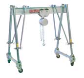
garage.  Ideally, I could rent a portable gantry and chain hoist.  Just lift the grinder off of the trailer and drive the trailer out from under it.  The problem with this was the scarcity of gantrys for rent.  I finally found them at Sunbelt Rentals.  They carry a good gantry crane, but it comes at 3 parts to rent.  The gantry itself, a trolley, and the hoist.  All told about $170 a day.  I would have gone for it despite the absurd price, but none of the local stores had all three parts in one location.  I had priced renting a forklift during the previous week and that was only $130 a day.  However you do pay for propane and delivery - which brought it up to a whopping $370 for a day's rental.  On the plus side, I rented on Saturday morning and got to keep the forklift until they picked it up on Monday afternoon.

Since I had next to no experience with forklifts, I wasn't about to try and balance the machine on the forks to make the lift.  Well, that and the fact that the surface grinder was in the center of a very long trailer and the fender was blocking direct access from the side. The forklift that put it on the trailer had much longer forks than the one I rented.  I decided that the best approach was to attach chains to the forks and lift it as I would with a gantry.  The chains were kept from slipping on the forks by using my vast assortment of C clamps.  Having my son home on leave from the Army was a big help as well.  During the week, I had removed the table from the grinder so I could get a look at the ways.  This also served to make the grinder less top-heavy.  I also had removed a few more items from the top of the grinder to lower the center of gravity.

Once we were sure that we had take all safety precautions, the lift,moving the trailer and setting the grinder back down took all of 5minutes.  Then lifting it from the bottom a couple inches from the ground and moving it into the garage took another few minutes. The rest of the afternoon was spent playing with the forklift and cleaning up the grinder.

DoAll D624-8 DoAll D624-8
Forklift moved into position.  Glad I got the long forks.
Yes, 2 Dodge trucks.  Hemi for my son and diesel for dad.
We made it.  Safe in the garage.
DoAll D624-8 DoAll D624-8
What have I done?  This thing is huge!
Night has fallen and I'm still amazed it's here.
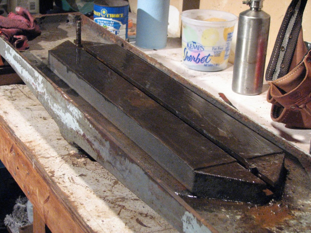
Scraping
DoAll D624-8
The first good look at the table (X axis) ways.
Interesting pattern. Some wear on each side of center.
You can also see the wavy line that mirrors the lube channel.

It's important that this surface grinder grinds as accurately as I can make it.  So, with this in mind and all of the reading,practicing and scraping I have been doing over the last year or so, I had decided to scrape the ways.  As I mentioned, I thought that the ways scraping marks were deeper and more pronounced than I had expected but they were not worn away for much of the length of the table.  My initial thoughts were that the scraping should go pretty quickly and that I would just be doing a light"clean-up" to scrape the less worn areas down to the depth of the more worn areas.  There was a bit of crud build-up opposite the wavy grooves that connect the lube holes on the ways.  This appeared to be old way lube that had dried out.  I knocked off the majority of it with a fine Arkansas stone, then checked the ways with a 3 foot Collins Microflat granite straight edge.  What I found surprised me.  The center section of the table ways was a bit higher than the ends and that there were two depressions about 12 inches from the center on either side. This didn't make any sense.  One would think that the majority of weight would be under the heavy chuck in the center of the table.  As the table ways moved back and forth across the stationary top ways of the saddle, the ends of the table's ways would overhang the ends of the saddle as a long work piece was ground.  No contact equals no wear, so by my way of thinking, the ends of the table's ways should be less worn than the center.  I blued up the ways to try a reverse print.  This is where the ways are covered in blue and then you slide the straight edge an inch or so across the ways to rub the blue off of the high spots.  This produces shiny silver spots on the light blue background. This check of the ways showed the same as before.  Center is high (not worn), slight dips about 12 inches out from center, and the ends are low (worn).  What the heck!?!  I sat down with Edward Connelly's book,  Machine Tool Reconditioning, and reread a couple sections on checking for wear.  He did mention circumstances where the end of the ways wear more than the center, but this was in a situation where the sliding ways were shorter than the stationary ways - like a lathe saddle (short sliding ways) on the lathe bed (long stationary ways).  I reread the surface grinder section and found that he thought that the wear I should have was the opposite of what I was seeing.  I then considered that I hadn't removed the magnetic chuck from the table yet.  Could it be that the chuck was warping the table?

d_table1
d_table2
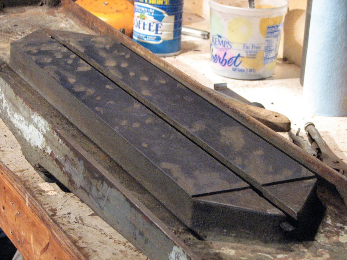
Initial checking of the flat way.  Center is high.
Stripping it down.  All of the splash guards are still intact.
d_table3
d_table4
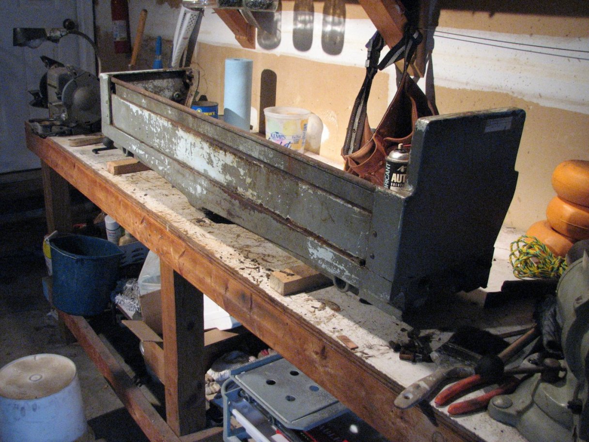
A bit of rust and corrosion and 2stuck T-bolts
Soaking the table in WD40. The bolts will be cut and drilled.
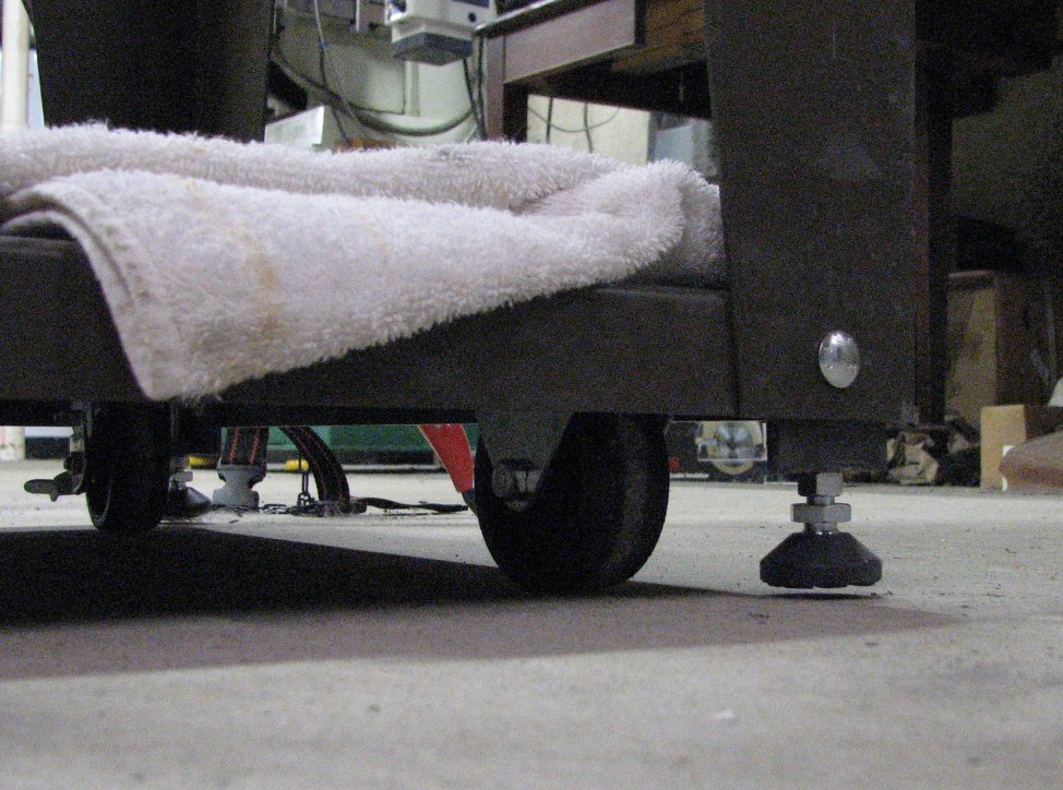
I needed to remove the chuck, but the 6" X 24" fine pole magnetic chuck didn't seem to want to come off of the table easily.  It looked like it had been on there forever. I soaked the 2 bolts that held the end clamps with rust penetrator and let the stuff soak in.  While I was waiting for it to work, I turned my attention to the top flat ways of the saddle.  I cleaned, then stoned the top flat way and then cleaned the 3 foot straight edge.  I blued up the straight edge and took a print.  Ends high, center low.  The opposite condition of the table.  I set a piece of heavy duty aluminum foil on the center of the ways and set the straight edge back down.  I tried to pivot the straightedge and it turned, pivoting on the foil.  This told me that the high spot was now the foil and since the foil was about 0.0009", the difference between the low center and high ends was less than 9ten-thousandths of an inch.  While just under one thousandth of an inch difference between the height of the center of the ways and the ends is too much, the fact that the center is low and the ends are high isn't necessarily bad in this situation. 
Connelly's book,  has a suggestion for increasing the life of certain types of ways.  He suggests that when scraping stationary ways that are shorter in length than the sliding ways that ride on them (as in this situation or as with the top saddle ways under the table ways on a Bridgeport-type mill), having the ends of the stationary ways high will keep them from becoming convex and allowing the table to rock for a longer period of time. This suggestion would also work for the opposite situation where shorter sliding ways slid on long stationary ways (like the example of the lathe saddle sliding on the lathe bed). The ends of the saddle could be scraped to be a bit high.  While he doesn't give a hard and fast rule for the amount that the ends should be higher than the center, my guess would be a couple ten-thousandths at the most and just having better bearing on the ends than the center for lighter loads.  The almost one thousandth inch difference I found by pivoting the straight edge on the aluminum foil is too much, I think,for this situation.

Speaking of checking for high spots, the easiest way I've found for checking for high spots is to try and pivot a known flat straight edge on the work to be checked.  The straight edge will pivot on the highest point.  If the straight edge pivots from the opposite end from the end you are grasping or pushing, the surface is concave.  If the straight edge pivots from a point about 1/4 the length of the straight edge's total length and if that spot is at the opposite end from which you are grasping or pushing, then the surface of the work is flat - or close to it.  If it pivots from the center, the surface is convex.  Once you've done this enough times to recognize the patterns, you'll find that you can even estimate how high the high spot is.

Back to the table and chuck.  Despite the soaking,the T-bolts that held the magnetic chuck to the table were not going to move.  I was going to need to resort to cutting the bolts to remove them.  Before doing this, I wanted to document what was going to happen to the table and ways when I removed the chuck. With the magnetic chuck still attached to the table, I measured the ways for flatness.  I could insert a 0.002" feeler gage under either end of the straight edge without the center lifting off the ways.  Once I cut through the bolts to crack loose the chuck (easier said than done),I rechecked the ways.  Now I could just get a piece of 0.0015" feeler gage under the center of the straightedge.  It would appear that the chuck had been holding uneven pressure on the table.  I don't know if some crud got caught between the chuck and table or if they just cranked the mounting bolts down way too tight, but whatever it was caused the table to bow by about 5½ thousandths of an inch. To make matters more interesting, after removing the chuck from the table there was a mess of rust and corrosion on the bottom of the chuck and on the table top.  Once all the scraping has been completed, these will require resurfacing, but in the meantime I just scraped the table top flat enough to keep the proper parallel relationship between the table and ways. 

As with most big projects, there are little projects that need to be done to realize your goals. To check the parallel relationship between the table top and the ways, I would need a level surface and a sensitive level.  My Starret "A" quality surface plate is on a wheeled plate stand.  This is nice for moving it around the shop,but doesn't help to level it.  I needed to add some adjustable feet to allow me to level it.  I didn't want to drill any extra holes in the new stand, so I made up some angle iron pieces to fit the existing bolt holes.  I brazed some triangular plates on the ends of the angle iron, drilled and tapped them to accept the leveling feet, and gave the angle iron a coat of paint.  I can now screw the adjusters up and roll the surface plate around the shop or lower the adjusters and make the plate level.  Perfect.

splate_pad
Leveling feet in the up position and we can move the stand.
Screw the adjusters down and the plate and stand can be leveled.

With a level work surface now available, I scraped the top of the table until I had bearing in all four corners.  While you might think from the look of the table that this would have been a big job, in reality, it went quickly.  The WD40 loosened up the rust and corrosion and I used a pull scraper to clean up the majority of the gunk.  I used the granite straight edge and Prussian blue to indicate the high spots and lightly scraped the T-slotted table top.  Scraping a ground surface is difficult as the scraper doesn't want to bite on the ground surface, but by diamond honing the scraper blade with 1200 grit paste on a glass plate after the initial sharpening, the blade is able to dig in rather than skip over the cast iron surface.  I removed enough high spots to see the plane that was developing.  Had I continued to scrape, it would have improved the surface bearing, but the table still would have been the same plane.  My goal was to find the plane and have it sit flat on the leveled surface plate.  With my box level (0.0002" per 10") I was able to check the flat ways 'relationship to the table.  I used a pair of hand scraped V blocks to support the level in checking the inverted V ways.  As it turned out and as I would have hoped, the table was parallel to the ways within a single graduation of my level.  So even though someone had cranked the chuck clamps too tight and put a bow in the table that ended up wearing the ways in places where there shouldn't have been much wear, the overall alignment of the table to ways was good. As a plus, or maybe a design feature,  the T-slotted table was level with the raised rail that surrounds the top of the table (after a little removal of decades of paint).  This meant it would be trivial to use some wedges to level the grinder table on the work bench in the garage.  This would allow me to keep the ways level with the T-slotted table as I scraped.

As I imagined when reading Connelly's book and again when I started scraping this grinder, the actual scraping would be the easy task.  The hard part would be keeping the relationship of the parts true.  As a rather simple example, consider that when scraping a flat way and an inverted V way, like I am doing on the table, the V and the flat need to be lowered (scraped) at different rates.  If you scrape
each side of the V way and remove0.001", you must remove 0.0014" from the flat way.to keep the relationship level.  To state the reciprocal, if you remove 0.001"from the flat way, you would need to remove 0.00071" from each of the 45° V ways to keep the table top from ending up tilted fore to aft. The other difficulty in keeping this relationship between the flat and V ways correct is finding a point to measure from.  If I lay a straightedge across the flat way and extending over the inverted V way, there is about an eighth inch of air between the top of the inverted V ways.  On the saddle, a straight edge laid on the flat way extending toward the V ways ends up being below the V. The only way I think I will be able to track the alignment between the two is make a jig, or a pair of jigs that will fit the saddle's upper ways and the table's ways.  From my reading, this appears to be a standard procedure.  The other standard way to check the alignment is to scrape both table ways using the 1.4:1relationship for flat to V ways, then use the table as the template for checking the saddle alignment.  I will use both of these methods,with using the table as a template and its relationship with the spindle datum plane as the final criteria.  I hope to provide more information on how I accomplish this as I get a little further along in scraping.

d_table5
d_table6
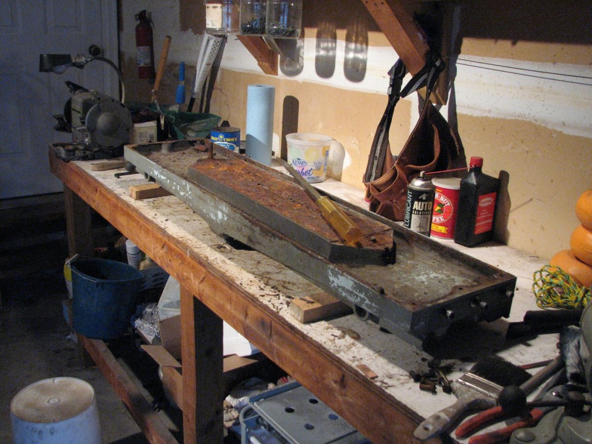
All that's left of the two T bolts after drilling and beating.
The table top is scraped flat enough to sit level on the surface plate.
d_table7
d_table8
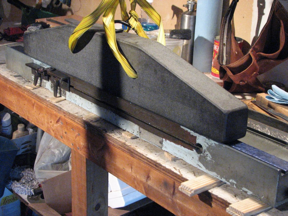
With wooden wedges in place the table is level and I can proceed with scraping the ways flat and true with each other.
After many cycles of scraping, the high spots are distributed evenly across the length of the ways. Now I begin to scrape for bearing.

The table has
almost4foot ways (47") and my straight edge is only 3 feet.  Yes, a 4 or5 foot straight edge would be better, but you use what you have.  The Collins Microflat straightedge is 36-1/4" long by 3" wide and about 7" tall in the center. It is pretty heavy to easily place and manipulate on the ways by hand,so I have it hung on some nylon strapping and attached to my engine hoist.  It is now easier to lower it down on the ways, slide it to mark the high spots and lift it off.  With a 3 foot straight edge on a 4 foot surface, I work in cycles of three.  The first cycle I mark the center then lift the straight edge, scrape the section that was marked and clean it. The next step is to place the straight edge on the ways and line up with the left end.  I scrape the end 5 1/2" that wasn't scraped in the first pass and also scrape any high spots found n the left half of the table.  I don't scrape anything past the half-way point on the right side.  The last step is to mark and scrape the right side of the table, again focusing my attention on the right 51/2" and any high spots up to the 1/2 way point.  Then the cycle starts over.  When the area under all three steps shows an even distribution of high spots, I know that the way is flat and can start to work on improving the surface of the way.  This entails making sure that I have high spots over the width of the way's inch and a half surface.  If I go for 16 bearing spots per inch squared, I'll have a spot every 1/4" - more is OK, but I'd like not to have the distance to be any more than a quarter inch between spots.

d_table9
More reverse spotting.  I've gotten to the point that the way is beginning to look good.  The groupings are still a bit uneven, but they're getting better.  A few more cycles will correct this.

Judging by the amount of scraping I have done over the past weeks, it is going to take a while to get the lower table and upper saddle ways to the flatness I am looking for.  I have been using a lot of pressure on the scraper and digging as deep as I can while still keeping precise control of the scraper.  Cast iron shavings are flying everywhere, but I still have over a half-thousandth to go after about 80 cycles on the table's flat way.  I'm only about20cycles in on the top of the saddle's flat way.  I have some jigs to build from cast iron stock and scrape to surface plate quality, but these shouldn't take too long as the surfaces are small and the jigs can be moved easily to assist in scraping from 3 directions to get the best surface quality.  As I said, I hope to update this article as I progress.


Powering the Grinder
This grinder has 3 3-phase motors.  One for the spindle, one for the hydraulic pump, and one for the coolant pump.  As with most newer residential homes (we had ours built in 1990) it has 120/240single phase.  I am going to need a way to power these three phase motors with a single phase supply.  I had come across this situation on many a bulletin board post over the last few years, but never spent too much time looking into it.  Now I needed to knowhow this worked.

From what I've read, there are two ways to go about getting three phase from a single phase source.  One is a variable frequency drive(VFD) and the other is a phase converter.  From what I've read,the VFD is better suited to powering a single motor and a phase converter is better when you have multiple motors.  The phase converters break down to static and rotary.  As a quick preface to phase converters, it is necessary to know that you can run a three phase motor on single phase power as long as you have a way to initially start the motor spinning.  Once it is spinning, the single phase power will keep it spinning.  It just doesn't have quite the power or smoothness that it would if it were powered by three phase power.  I've heard between 1/2 to 2/3 its rated horse power.  A static phase converter is nothing more than a way to get a three phase motor spinning while being powered by a single phase source.  This is usually done by connecting a electrolytic capacitor  between one hot wire or "leg" of your 220 volt single phase source and the second motor wire, while the other leg of the single phase source connects to the third (and last) wire of the motor.  The current from the line with the capacitor creates an imbalance in the magnetic field of the motor and causes the motor to spin.  Once spinning, there is a automatic switch in the static phase converter to remove the capacitor from the circuit and the three phase motor continues spinning using the two hot wires from your 220 single phase source.

A rotary phase converter is a static phase converter with an idler motor added to the system.  The connections described for the static converter are the same, except that the motor you are hooking the static converter up to doesn't mechanically power anything. What that idler motor does do is to create an artificial third leg of current.  If you then hook the motor of your three phase lathe or grinder in parallel to the idler motor, your lathe or grinder receives usable three phase power.  This is a simple example, but one that will work.  You can also add a few more parts to  "tune" the power coming from the three legs of the idler motor using oil filled"run" capacitors to help ensure that the voltage on all three legs are similar.  This will allow you to use your rotary phase converter to power a CNC mill or lathe without problems you might experience with less refined phase converters.

I really considered going with a VFD even though it would have been a bit of a chore to set up different programs to deal with the three motors on the grinder, but if I went with a rotary phase converter, I'd have three phase available if a lathe or mill happened to follow me home.

To properly size a phase converter, you need to know what kind of load will be placed on it.  This is generally as easy as figuring 1-1/2to 2 times the horse power of the largest motor you will run, or the total of motors in my case.  The total hp for the grinder is 2.833 (1.5 + 1 + .33), so I decided on a 5 hp idler.  I considered the merits of purchasing a working converter or building my own.  I didn't really need another project right now, but the reasonably priced phase converters were not that inexpensive for what you got.  The general consensus of folks who know a lot more about this than I do warned that many of the less expensive converters used marginally rated parts to save on cost.  On the other side of that coin, the well built converters would set me back almost as much as I paid for the grinder.  I looked at some circuits and priced the parts and found that for the price of an inexpensive converter, I could build one that was rated as well as the best available.  As I said, I decided on a 5 hp idler.  That had as much to do with the fact that there was a 5 hp three phase motor available for a good price as for it satisfying the power requirements of the grinder.

So, here I am in the middle of a few projects.  Scraping the ways of the grinder and then getting it running so I can check it over and building the three phase converter that will power it.  I guess I have my work cut out for me for the foreseeable future.

More to come as I get to it.
Grinder 1
Grinder 2 Grinder 3 Grinder 4 Grinder 5 Grinder 6 Grinder 7