HOME
What's New


Workshop Stuff

Workshop

Moving the mill

Spindle Noises

ShumaTech Digital Readout

ShumaTech DRO Continued

ShumaTech
DRO-350 Repairs


South Bend 9" Lathe

South Bend 405 Lathe Bench

Grizzly Mill Revisited

Surface Grinder Rebuild

Surface Grinder Continued

Grinder April 6, 2008

Grinder April 20, 2008

Grinder August, 2008

Grinder September, 2008

Grinder November, 2008

Grizzly G3103 Mill
Rebuild

Grizzly G3103 Mill
Rebuild - Part 2

Moving the Shop

Moving the Shop 2

Bringing Home a Sheldon 12" Shaper

Sheldon 12" Shaper 2

Sheldon 12" Shaper 3

Sheldon 12" Shaper 4

Sheldon 12" Shaper 5

Sheldon 12" Shaper 6

Sheldon 12" Shaper 7

Sheldon 12" Shaper 8

Sheldon 12" Shaper 9

Way Alignment Tool


Email Jim


 workshop.gif
Grizzly G3103 Revisited
A Year with the Mill

 
It has been over a year since I purchased the Grizzly Mill and documented the task of moving it into the basement, getting it set up,and the few issues I had with getting the mill running in an acceptable fashion.  Well, make that and acceptable fashion for my knowledge at the time. During that time, I have had many email from folks interested in purchasing a G3101 mill of their own.  The question I'm  most often asked is "would I do it again?"  The answer is both yes and no. Yes, it has been (and is still) a fun project, an acceptable product,and having this mill and getting back into metal-working feels really good. However, if you ask me, "Knowing what you know now, would you purchase another G3103?"  The answer is probably no, but not because it hasn't done what it was supposed to do.  Given its limitations (size and rigidity), it is an acceptable product and given its cost, it is a darn attractive purchase.  The reason is two-fold, 1.  I have (again) fallen in love with older machine tools and even if the Grizzly out-performed an older piece, the satisfaction I get from bringing an older piece of machinery back to good running condition and then using it to make something useful out-weighs a piece that is already in perfect condition.  2. I am finding that I want to work on larger pieces than the G3103 will allow.  A 50+ inch table would be more to my liking and this Grizz is only about 26 inches.

So, what about the mill? What about the problems I've experienced?  What do I think you should expect if you buy one of these?

A project.  The mill is a project.  It isn't quite ready to make chips when it is unpacked from the crate.  If my experiences and the experiences I have heard about first hand are normal, you will need to do a bit of work before you can use the mill.  How much work depends on a bit of luck and how accurate you want or need the mill to be.

I have had the pleasure to converse with many folks who were considering a G3103 and a dozen or more folks who have purchased the G3103 and have kept in touch for, at least, long enough to get the mill set up and start making chips.  Every one of those people have had at least one issue with the mill that needed to be addressed before it could be used. Most were relatively minor issues, but if you purchase one of the G3101 mills or their counterparts sold by other retailers,it would seem that some work is going to be needed before you can start making chips.   Here are some of the issues that I know about from my mill or from conversations with others with the same mill

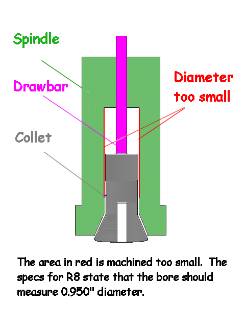
There seems to be a fairly recent batch of Grizzly mills with the inside diameter of the R8 profile in the spindle that have not been bored large enough to accept anything other than the face mill that is supplied by the manufacturer with the G3103.  This is the top of the bore ( the hole - to make it as clear as I can), above the locater pin inside the spindle that an R8 shanked tool would fit into.  This is the area where the draw bar attaches to the collet or holder.  The specs for the R8 are that the diameter of the hole at the top where the draw bar meets the tool is to be 0.950 inches.  I don't know what the tolerance is on this, but the second or third to the last person who experienced this, figured the hole in his spindle was bored to about 0.948"or so.  He tried honing it out with a two stone automotive brake hone to no avail, but said that it was a cheap hone.  The stones wore out before he was able to enlarge the hole.  Grizzly customer support recommended either sending the spindle and quill assembly back to them for resizing or to wrap some sandpaper around a stick and shove it up into the hole with the mill running.  He opted for the second and while he was able to increase the diameter enough to get his collets to fit, the locater pin was sanded down in the process.  I would imagine that this will mean that the quill and spindle is going to make the trip to Grizzly anyway for a locater pin replacement.  On a new mill, I would be very hesitant to press out the spindle from the quill without having some replacement bearings handy and this assumes that you have a press with sufficient force to press the spindle out in the first place.  I guess the end result of this is if you have a Grizzly mill coming to you, you would be advised to have a couple of R8 collets or end mill holders to test fit and make sure that your spindle hole isn't too small.

spindle bore too small

Other items I have heard of and personally experienced is that the belts aren't of the best quality.  They are made from pretty poor quality rubber. They shed rubber dust like crazy and tend to vibrate or maybe pass the vibrations from the motor to the spindle.  A new set of belts will fix this.

Belt alignment.  My idler pulley was aligned to be about half a belt width too low.  A couple of flat washers under the idler pulley hold-down bolt fixed the issue.  You might also take a look at the motor adjusting mechanism. It is adjusted with a clamp and pivots on a hinge.  My motor was tilted a bit and required a couple more washers to level it out.  I also lock the adjustment,rather than letting the motor self-adjust so as not to put full tension on the belts.  I find that leaving the belts a bit on the loose side makes for less vibrations passed to the spindle.  This results in a nicer finish when making finishing cuts. 

The one-shot lubrication system is in need of a little help as well.  My system came with no check valves after the pump. If you fill the tank with way lube and give it a couple of squirts, then walk away, when you return the next day, all of the lube has been siphoned out of the tank and you have a nice mess on your hands. I added a one-way check valve that requires pressure to open it. This seems to fix the siphoning problem, but I still lost all of the way lube in the hoses (after the valve).  This means you must pump the lube a few times to fill the hoses.  Since there are long and short hoses, while you are filling the longer hoses, the lube has already filled the shorter ones and is now leaking from the ways to the floor or machine's base.  (Update) After trying a bunch of different check valves, I have come up with the perfect setup for fixing the one-shot lube system.  A total of 7 check valves are used.  All of the lines now retain their way lube and it only takes about a quarter to half a pump to lube the ways.  No more siphoning and no more mess.  I am looking for a cheaper source for these parts and will post if and when I find a better deal.

The problem that I think is the biggest concern is an issue that I have heard from others and also experienced on my own mill. It concerns the general alignment of the machine.  Generally speaking, the mills I have encountered are within a thousandth on all three axes over small distances - say 4 to 6 inches.  The tolerances tend to get worse as you reach the end of travel on both the X and Y axes. However, in many cases I've encountered, the operator is the cause for parts that don't end up being square.  I've had a few email in which the person complained that he couldn't machine a perfectly square block and what could he do to improve the accuracy of the machine.  I too have been through the trials of machining a part to very fine tolerances and as the tolerance gets smaller, every thing becomes critical.  Leveling the mill and then tramming the spindle to table alignment is the first place to start.  Once you have the spindle perpendicular to the table, you can move on to your milling vise.  A spec of swarf or a ding in the table under the vise can throw all of the trial and error tramming work right out the window, so before you mount the vise, you may need to stone any raised dings in the table to make them flat.  Check the bottom of the vise for dings, chips, or dirt.  Once the vise is clean and free of bumps,mount it and use your machinist's level to check it in all directions.  My 4 inch vise was out by 0.001"  due to a ding in the rails (ways) that the movable jaw rides on.  This is also where the work would sit if parallels were not being used.  Parallels.  If you are working with parallels to machine your block, make sure that they match and that they are square and level.  My inexpensive set were mismatched in height by 0.0005" at one end, in one direction and if I reversed one of the parallels, they were out by 0.001.  This can be repaired, but a reference plate and "tenths" (0.0001") reading indicator is necessary for checking them. An import granite surface plate is inexpensive - less than $50 -and a necessary tool if you are looking for accuracy.  Once you know how much material you need to remove, a stone, or even better, a scraper and a stone can be used to match them to a tenth or better.  If you have a flat surface and some diamond paste, you can also lap the parallels back to near perfect, but you will still need a surface plate and indicator to check them. Trying to lap anything flat without a known flat surface to check it against is an exercise in futility. With a granite surface plate and some Prussian blue, the process is quite easy. 
1. Clean the surface plate spotless.  I use Starrett's cleaner,but a window cleaner will work in a pinch.
2.  With a bit of felt or some lintless applicator, spread an even amount of bluing over a square of the plate that is a few inches larger than the piece you are going to check.
3. If you have a rubber roller as used to ink a printing press, great, if not, I have found that I small very short nap paint roller will do an acceptable job.  Roll the bluing out until the thickness of the blue is uniform in depth/color.
4. Clean the piece you are checking.  It should be spotless.
5. Place the piece straight down on the blued surface. 
6. Lightly nudge it about a half inch in all directions.  Do not apply downward pressure, let gravity be the only downward force.
7.  Lift one side of the piece to break the bond and the tendency for the part to stick to the bluing, then lift the piece straight off.  Do NOT slide it off.
8. The areas that have blue transferred to them are the high spots. 
9. Remove the high spots with whatever means you are using - lap, file,diamond hone, or scraper.
10. Clean everything and start over.

If you are truing up a parallel, once 70% or more of the surface marks blue and the blue is evenly distributed across the whole face of the parallel, you can move on to the other side.  It is a good idea to check the height of the parallel on the surface plate with your tenths indicator every couple of cycles to make sure that the two opposite sides stay parallel to each other and square to the sides.  This is a time consuming process, but if you have more time than money, you can produce a parallel every bit as true as the $90 pair of 1.0" X0.25" X 6" parallels that Taft-Pierce Metrology sells (0.0002" size tolerance and 0.0001" parallelism)

Once you have everything adjusted to the best of your ability and your vise is level and square with the spindle, you should be ready to see what kind of accuracy you can hold when machining your cube.  With my mill, on small blocks under four inches, I can hold to less than 0.001" with regularity.  With blocks over eight inches, my one thousandth doubles or triples.  This leads us to the next item.

One of the folks who wrote me complained that the Y axis wasn't smooth and tended to bind when cranked close to the inner-most and outer-most limits.  I experienced the same problem with my Y axis and found that there were some burrs on the gib. My temporary fix was, in retrospect, a poor way to go about fixing the problem.  I used some 400, 600, and 1000 grit wet and dry sandpaper to smooth out the burrs on the gib, then re-adjusted the gib so that the Y axis was tight enough not to have any slop, but not tight enough to bind.   I have heard of others who have done similar repairs and there is even a page on a site for a pretty well known Chinese bench mill that has an instruction page for "lapping the ways" of this bench mill.  He uses how smooth the action was as the criterion for success.  After much reading about reconditioning machinery, I think that this is not the way to go.  Knowing what I know now, I am of the opinion that nothing should be used on the machine ways without having a template that is at least as flat and true as you want your ways to be and preferably much more true than you require the ways to be. You may smooth out the surface of the linear bearing by sanding, but the trade off is that whatever accuracy you had will leave with the use of sandpaper unless you use the sandpaper in conjunction with a machinist's straight edge and bluing to check the progress of your work.  Even then, there are better tools for removing metal from the ways accurately.  Removing metal from the ways can be done with a planer, or a surface grinder, but the tried and true method that has been practiced for as long as there have been ways is to fit the linear bearings by scraping.

For the uninitiated, scraping is a process of using what looks like a square edged (instead of sharpened to a knife edge) chisel or scraper to scrape small amounts of metal from the ways and gibs until you have a surface with its highest points all in a single plane. Flat.  Depending on the pressure used and the keen-ness of the scraper, one can remove a few millionths to a few hundred-thousandths of metal in a pass. If you catch an edge of the scraper you can gouge it much deeper than that.  When an area is scraped, the uppermost surface may be only comprised of a dozen or more "points" per square inch that are in one flat plane and constitute the surface that the opposing way rides on.  That doesn't seem like much, but the surface surrounding these points may only be a hundred-thousandth of an inch lower, so to the eye and touch, it is smooth and flat.  Add to this that
there should be a film of lube/way oil on top of those points that is the real contact surface between the upper and lower way surfaces and you get an idea of how these few points can support the weight of the table and work piece..

After much reading and many months worth of practice, I am getting closer to making a proper repair to this issue.  I am going to scrape all of the ways on this mill flat and true to the best of my ability.  I would say "re-scrape", but not all of the ways on this mill were scraped in the first place.  All of the upward facing ways appear to be machined and the downward facing ways were machined or planed and somewhat scraped to fit.  Only the gibs are fully scraped on my mill and the scraping job is not one of the best I have seen and certainly not as good as the work I am now turning out.  I'm not patting my own back, but after 6 months of scraping almost every day, I am getting better at it - at least one would hope so.  The scraping on the G3103's gibs look like where I would be on my fifth to tenth cycle and I don't don't start getting a really nice surface until I've scraped a minimum of 30 cycles.

Having a machine tool table that is square and true to the spindle is fundamental to the accuracy of the tool.  While it is said that a good machinist can produce accurate work on an inaccurate machine,the farther out of square the machine is the harder it gets.  It could be argued that a hobby machinist doesn't need accuracy measured in ten-thousandths of an inch, but it would depend on what you are building.  I have been making some modifications to my lathe and building some accessories for both the mill and lathe.  With these projects, I want as much accuracy as I can possibly get, as an out-of-square boring bar holder will bore inaccurate holes.  The same situation holds true for the tool post grinder I built, and making the modifications (adding needle bearings and slotting the lead screw)on the South Bend 9" model A and B type saddle and apron I added to the old "405" workshop lathe.  With these projects, there is a big difference in performance and "repeatability" if the tolerances are kept to a minimum.

I should stop here for a moment and say that my mill seems to be a bit more out of specifications that others that I have heard about. The height of my table changes by as much as 0.0035" from full left to full right (X axis).  On the Y axis, mills are designed to have the table a small amount high (as opposed to being level) on the side opposite from the mill's column (or low on the side closest to the column).  The specs for this can be from plus zero to plus one thousandth inch or so for the relative height of the front-most edge of the table - depending on the mill - according to Edward Connelly in  one of the best books on the subject, Reconditioning Machine Tools.  The Y axis on my Grizzly is high by a few thousandths over the relatively short 6 inch table width (Y axis).  My mill is pretty close to being square if I work within about a four inch square in the center of the table.  If I try to mill a foot-long piece, there will be a minimum of 0.002" difference in height when comparing the end measurements.  Some of this discrepancy is that the table itself that is not flat and some can be attributed to the ways.  There is really no way of knowing the exact scope of the problem until I strip the mill down for measurement.  To be able make these measurements, I have had to purchase a few tools (0.00005" and 0.0001"reading indicators, granite inspection block, angle plates, and a couple precision levels) and make the remaining tools that were either not available or were too costly to buy (cast iron straight edges, dovetail angle templates, custom precision level for tight areas).  I am finishing up on making my tools and when I am done, it will be time to strip down the mill and measure it.  The next step will be to scrape the ways to get the machine as close to square and plumb as I can.


By the way, if you are interested in learning about reconditioning machine tools by scraping, Edward Connelly's book
reconditioning machine Tools,  is a pretty impressive work.  It doesn't have a lot of information on the technique of scraping, but does give you enough technique to get you started.  Much of the book is devoted to determining measurement.  He also has plenty of information on the various designs of linear bearings and how to deal with them.  It was a rather hard book to read as his writing style is long-winded, dry, and reminds me of my hated high school grammar texts.  However, my dislikes in writing style aside, the book is full of great information that I have not been able to find elsewhere.  He illustrates how to properly measure the linear bearing surfaces of mills, lathes, and surface grinders. He documents what kind of tools and templates you will need to purchase or make and - just as important - how to use these tools to check and restore the machines to a plumb, parallel, and square condition.

I have been scraping between 2 to 12 hours a day, pretty much non-stop since July and I've found that it is both easier and harder than I expected.  Easier, as in actually being able to scrape a straight line or be able to see the high points that need to be lowered by scraping.  Harder, as in tough on the body.  The first couple of weeks I was just sore from using muscles that don't get used that often - same muscles I use when I wax my truck.  Now, months later, my hand actually goes numb after a few hours of the repetition and I have to shake it out before I get the feeling back.  I now also have enough Prussian blue on a couple sets of shop clothes that it is getting hard to tell their original color.  (Well maybe that is a bit of an exaggeration, but close!)   I have found that given enough time, I can produce work that is flat (or more correctly, has many surface contact points in a single plane) with a ten-thousandth or two, between the highest and lowest points over a span of two feet,using no more than a granite plate, a few scrapers and some Prussian blue to mark the high spots.  It's pretty impressive to me that this is even possible.  I hope to document the process of my attempt to square up the mill, as I haven't come across any "in depth"scraping projects on the web yet.

I got carried away in writing about scraping and kind of strayed from the point of this page.  Anyway, all in all, I am still pretty pleased with the mill, however this mill isn't for everyone.  If you require a mill that is dead-on accurate out of the crate, this certainly isn't the case with mine.  As I said in the beginning of this piece, this mill is a project.  If you want a usable mill that is pretty well designed and you are willing to spend the time necessary to make it right, I don't think that there is another new mill in its price range that can touch it.