Sheldon 12"
Shaper - pg. 3
July 23 - August 17, 2015
In the last installment, I
had started scraping the bottom of the vise body due to the top of
the vise rails not being parallel with the shaper table. The first
picture below shows the bottom surface pretty much as I got it. I
had scraped off a couple dings in the upper right corner and
scraped/cleaned off some dried crud from the circular area where
the bottom of the vise
body surface makes contact with the ring on the top of the swivel
base. I had also scraped the little bit of metal on the lower left
edge of the casting that was preventing the rest of the surface
from touching the surface plate. As you can see in the expanded
picture from the small amount of red Canode ink on the upper right
and the lower left edge, there's not much contact with the
inked surface plate. It appears that the vise body has warped. The
cause of the warpage may be that some swarf got trapped under the
ring that contacts the vise body or maybe the jaw was cranked down
too hard on an uneven work-piece. The end result is that it isn't
flat. Unfortunately, I forgot to try some feeler gauges under the
corners opposite of where it shows color so I could have a record
of how much it was warped.

|

|
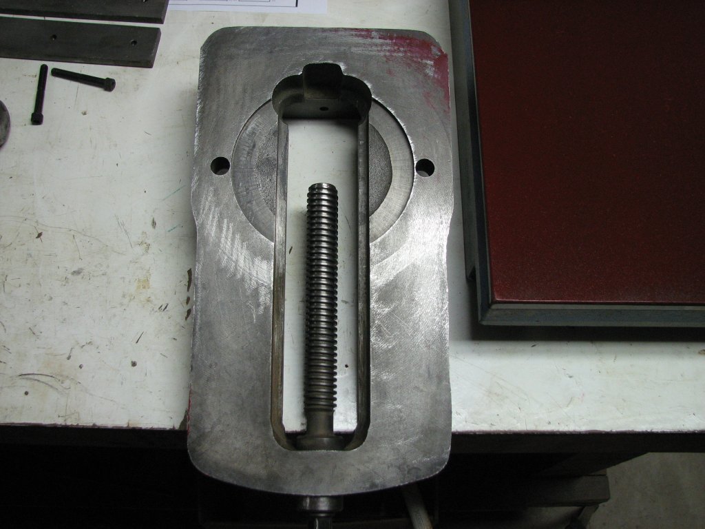
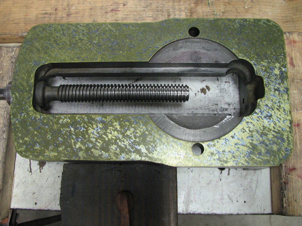
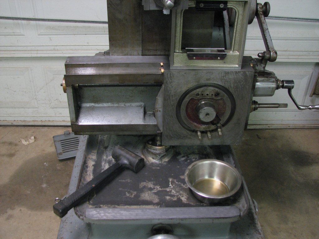
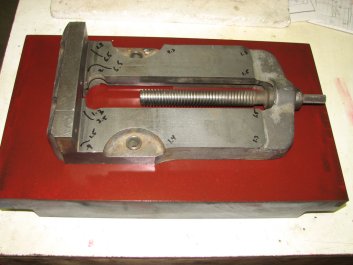
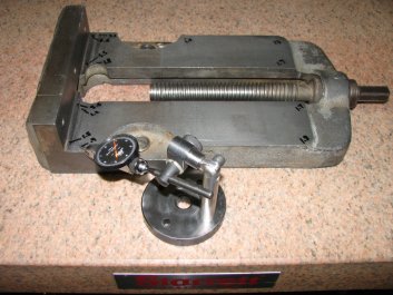
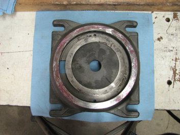
This
is the bottom of the vise body as received with only a
little scraping to clean up some dings.
Color in upper right and along the lower left edge.
|
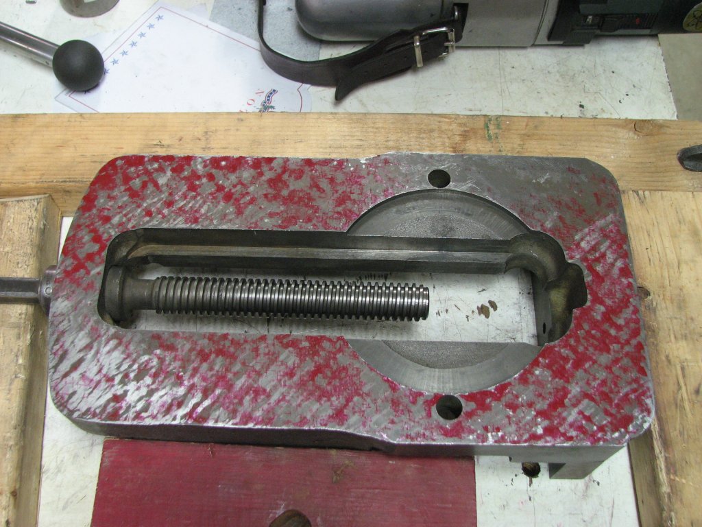
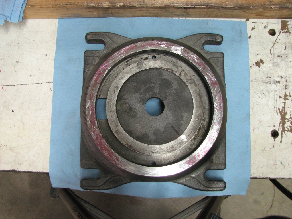
I
have a few cycles of scraping on the vise body and we
still don't have color in the upper corner.
|
After I had scraped a few scraping cycles, I put the vise
body on my best surface plate and measured the relative height of
the different areas of the vise rails. I then moved it back to the
smaller plate I use for marking and took the picture (left below).
You can see a line, parallel to the cast jaw, that separates the
original height of the rails from the worn or re-worked area. In
the lower left of the picture, the original surface under the
fixed jaw's removable face is 0.0006" higher than the worn area to
the right of it. On the other rail (top left of picture) the
difference has grown to 0.0037". Even without taking into
consideration that the vise body had warped, the difference in
height between the two rails is enough to cause errors in
machining parts.
A couple of scraping cycles later, I remeasured the tops of the
rails again. The second set of measurements were very similar to
the first. Trying to measure to ten-thousandths on a less than
smooth surface makes duplicating the exact same measurements
almost impossible, but they're close enough to let me know that I
need to get the bottom of the vise body flat and machine the top
of the rails.
|
|
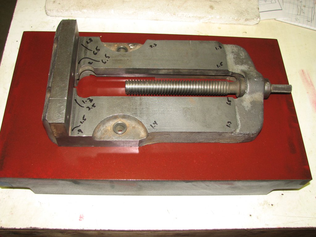
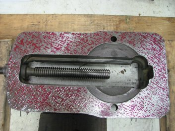
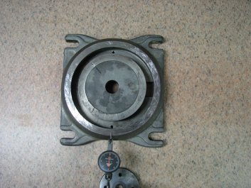
The
vise body is on the small plate I use for marking. The
numbers are the relative height in thousandths as measured
on my large plate.
|
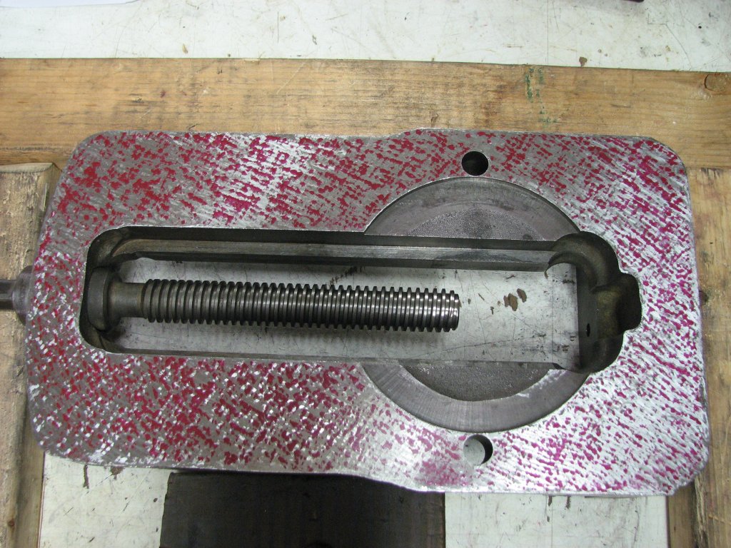
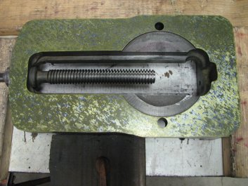
After a
few more cycles of scraping, the measurements of the
relative height are much the same. The top of the rails
will need some work.
|
After a few more passes of spotting with the red Canode fluid, I
decided that it was time to switch to Dykem Hi-Spot Blue. I like
the Dykem product better than the other brands of oil-based
Prussian blue I have tried. It seems to have a less greasy
consistency than the Permatex brand and retains its color better
when rolled on thinly. I also tried some stuff from a seller on
Ebay that I liked less than the Permatex. While a thin coat of
blue is better for refining the number of points per inch, it
comes at a price. The price is that it is very hard to see the ink
spots on the shiny scraped surface. Getting your lighting at a
proper angle helps, but applying a contrasting background color to
the surface you are spotting seems to help me more. I used yellow
Canode spotting fluid rubbed on and then buffed with a dry paper
shop towel in order to leave the smallest amount that still puts a
yellow haze on the scraped area. I then place the work on the
thinly inked Dykem covered surface plate and rub it very little to
transfer the blue on top of the yellow. The more you rub the work
on the inked surface plate, the more that the Dykem Hi Spot builds
up around the high points. This makes the area around the points
easier to see, but the increased spot size makes it tougher to
just scrape the tops off of the high points. When switching from
the thicker Canode red to the thinned out Prussian blue, you get a
much truer picture of the contact points per inch. After the
switch in marking mediums, I was now showing a lot more space
between the marking spots. I scraped about a dozen cycles
with the Prussian Blue and yellow before I moved on to the last
marking technique.
|
|
This
was taken after some more cycles. I'm beginning to get
some better coverage. I still have some sparse areas,
but they're beginning to fill in.
|
I
have switched to rubbing on a background of yellow
Canode and spotting with Dykem blue. I rubbed more for
this picture to show the spots, but the camera didn't
catch the lighter blue spots.
|
The last technique I used to mark for
finish scraping is reverse spotting. With this method, you
apply the spotting fluid directly to the work. I like to use
the Canode ink for this because I can buff most of it off
with a shop towel and end up with a very thin layer of the
ink. The thin coat water based Canode also doesn't transfer
to my clean surface plate as much as the oil based Dykem.
You then rub the work on an un-inked surface plate and you
end up with little silver points of shiny metal where the
Canode has been rubbed off. Now you can see exactly where
the work is contacting the plate. I wanted to be able to
show the whole bottom surface I was working on, but was
having trouble trying to figure out a way to photograph the
bottom of the vise showing all of the shiny spots at once. I
had the best luck by lowering the ISO setting on my camera
to 80 and only focusing of a small area of the vise. While
lowering the ISO made the picture very dark, you can see
some of the shiny spots that I see with my eyes. There are
even more spots in the brighter area than the picture is
showing, but this was the best picture out of a bunch that I
took. The remainder of the bottom of the vise body looks
similar to the small area I was able to photograph. In the
least densely scraped areas, there are about 18 points per
square inch. In the most dense area, where the ring of the
vise base will make contact with the vise body, there are 20
to 30 per square inch. My scraping of the vise's bottom
surface is a bit less even in points distribution than I'd
like, but I am a bit out of practice. However, the surface
is a whole lot better than when I started. As for the dark
picture and my lack of photography prowess, many of the
shiny spots didn't get captured by the camera. I'm not
surprised by this, as when I am trying to see the shiny
spots to scrape them, I have to constantly move my head
around to catch the reflection of light from each spot. It's
tough to get the camera to see what I see.
I scraped a few more passes after I took
the pictures, then declared the bottom surface vise body
bottom done. Time to move on to scraping the ring on the
base.

|

|
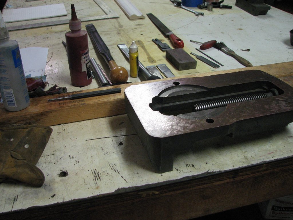
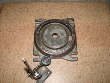
Reverse
spotting. In this picture, I was having trouble
getting the camera to see the spots due to the glare
on the scraped surface.
|
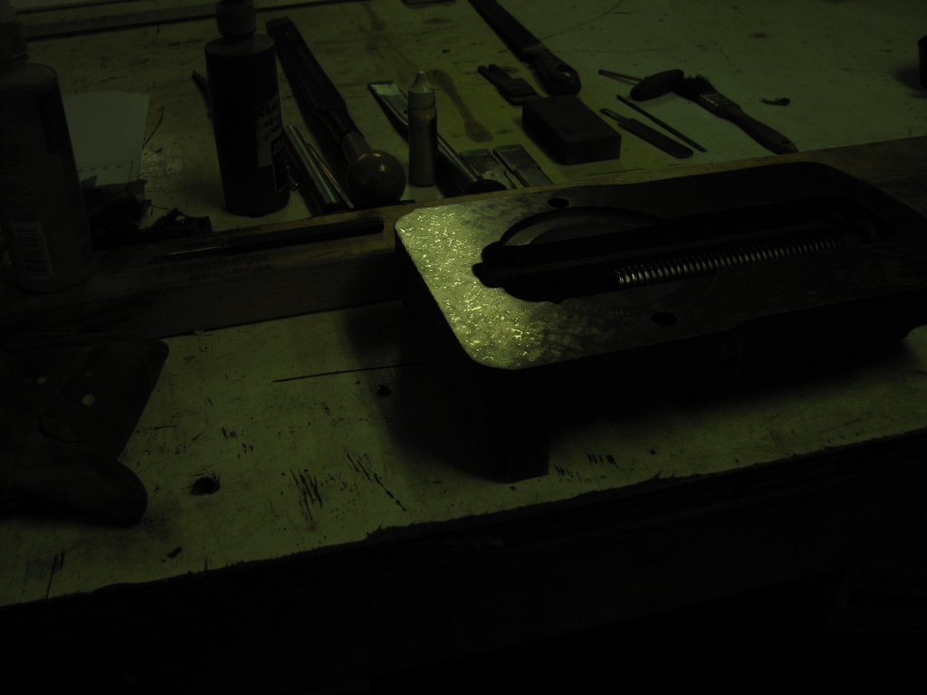
I
switched the camera's ISO setting down to 80 which
darkened the picture so you can see some of the light
reflecting off the high points.
|
In the last article, when I had finished scraping the bottom of
the swivel base, I had measured the difference in height
between the ring and the base at about a quarter thousandth -
0.00025" - higher on one side of the ring. This measurement was
taken around the center of the half inch wide ring. When I
re-measured the ring on both the inner and outer edges, I found
that I had a difference of a half a thousandth. This is still a
pretty small amount, but the goal was to get the ring as flat and
parallel to the bottom of the swivel base as possible. I dabbed a
few drops of red Canode on the vise body and rolled it out with a
one inch diameter, six inch wide paint roller to get ready to mark
the ring. Speaking of the paint roller, I use the ones that are
sold to paint behind toilets and other tight areas. Before I use
them for the first time, I roll them over duct tape to pull off
any loose material. I have one for each color and type of spotting
fluid and I keep them in plastic tubes when I am not using them.
When they get contaminated with flecks of metal, I pick off what I
can see, but eventually they start leaving the flecks on the
surface I am covering with spotting ink. When this happens, I
don't bother trying to cleaning them any further. I tried that
once and the roller still left metal on the surface I was inking.
Now I just replace the rollers when they get contaminated.
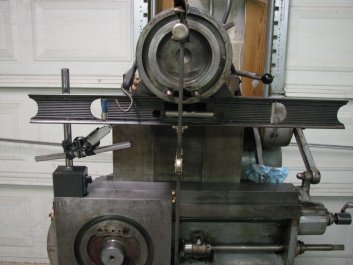
The vise body worked pretty well as a scraping master,
but I would have preferred to use a granite plate if
the center ring of the base didn't stick up above the
surface I was trying to mark. I have a cast iron
surface plate and a number of cast iron straight edges
- with and without angled sides for marking dovetails.
However, I like marking with granite better. It seems
to hold the marking fluid better and you don't stand
the chance of raising a burr on a granite surface.
However, using the vise body to mark the base ring was
the right tool for the job.
Before
I marked the ring, I measured the height of the ring
and made notes of the high areas, then did my marking
print. I concentrated my scraping on the high side of
the ring and re-measured its height after each pass.
This was a little tough to do as the ball point of the
DTI bounced around a bit due to the different depths
of my scrape marks as I measured around the ring. I
made a few more passes until the high points were
close to the same height around the ring. Since there
is a gap on the screw side of the vise body that I am
using to mark the ring, one section of the ring did
not get color on each spotting print. I decided that I
would rotate the vise body a quarter turn for each new
print so that after four scraping cycles, I had
covered all sections three times.
|
|
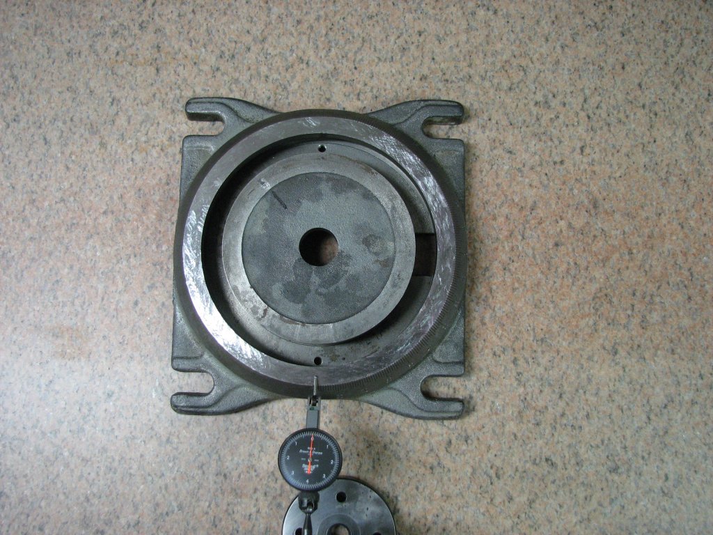
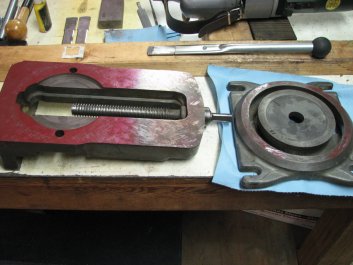
With
the vise body bottom scraped, it was time to use it
as a scraping master to help me scrape the vise's
base ring. After each scraping pass, the ring was
height checked on the surface plate.
|
The
total height of the ring was only out by half a
thousandth, so it didn't take many passes to get
color. The bottom of ring didn't get color due to
the gap between the vise rails.
|
When the height
was close to being even all the way around the ring,
I took four spotting prints without scraping. I just
cleaned off the previous ink, turned the vise 90
degrees and took another print. The prints were very
close to looking the same for each of the four
attempts, so it was time to start to refine the
surface. I sharpened up a few blades for my scraper.
I have a eight inch aluminum disk attached to a one
horsepower motor that I use for honing the carbide
blade tips. I use the outer race of a two inch
diameter ball bearing attached to a handle to apply
a mixture of oil and 1200 mesh diamond dust to the
disk. I press the bearing into the disk and let it
spin to embed the diamond dust. A couple passes of
the scraper blade over the disk keeps a mirror
finish on the blade tip. I then hone the flanks of
the carbide tip on a plate of glass coated with more
oil and diamond dust to get a nice crisp cutting
edge.
Since a sharp blade cuts much nicer than even a
slightly dull one, I used a newly sharpened blade to
scrape around the ring once. After re-spotting the
ring, I switched to another newly sharpened blade.
This went on for about a dozen passes until the
surface of the ring was only moving the needle of
the DTI less than a ten-thousandth between
individual scrape marks. There are a few divots
where I dug the scraper in a little too deep, but
the high points on the ring are now within 0.00015"
all the way around.
Right or wrong, I have scraped this vise with only
the smallest amount of difference between the height
of the points to the valleys beside them. I felt
there was no reason for oil pockets. When the vise
does get moved, or the swivel feature is used, the
slight wear that occurs won't come close to the wear
that the ram dovetails see. Eventually the surfaces
will wear, but by that time, it will be time to pass
the shaper on to someone else.
I made one final scraping pass, then checked the
ring height one more time. With the ring done, I
started thinking about how I will even out the top
surface of the vise rails. At the moment, I am
leaning toward using the shaper to resurface the
vise rails - provided that I can get the shaper to
be as accurate as I need for this job. To get the
rail top surfaces parallel to the table, I need to
make sure that the ram and cutting bit runs parallel
to the table. To get started on this, I needed to
make sure that my measuring tools were still
accurate after not being used for a while.
|
|
To check the ring height, I set
the DTI at zero and measure the height of
the ring all the way around. At this stage
there's about 0.0003" difference between
high and low areas.
|
For this picture, the height of
the ring is within 0.00015" all of the way
around. There are a couple scrapes that
are deeper, but they won't affect the
registration of the body on the ring.
|
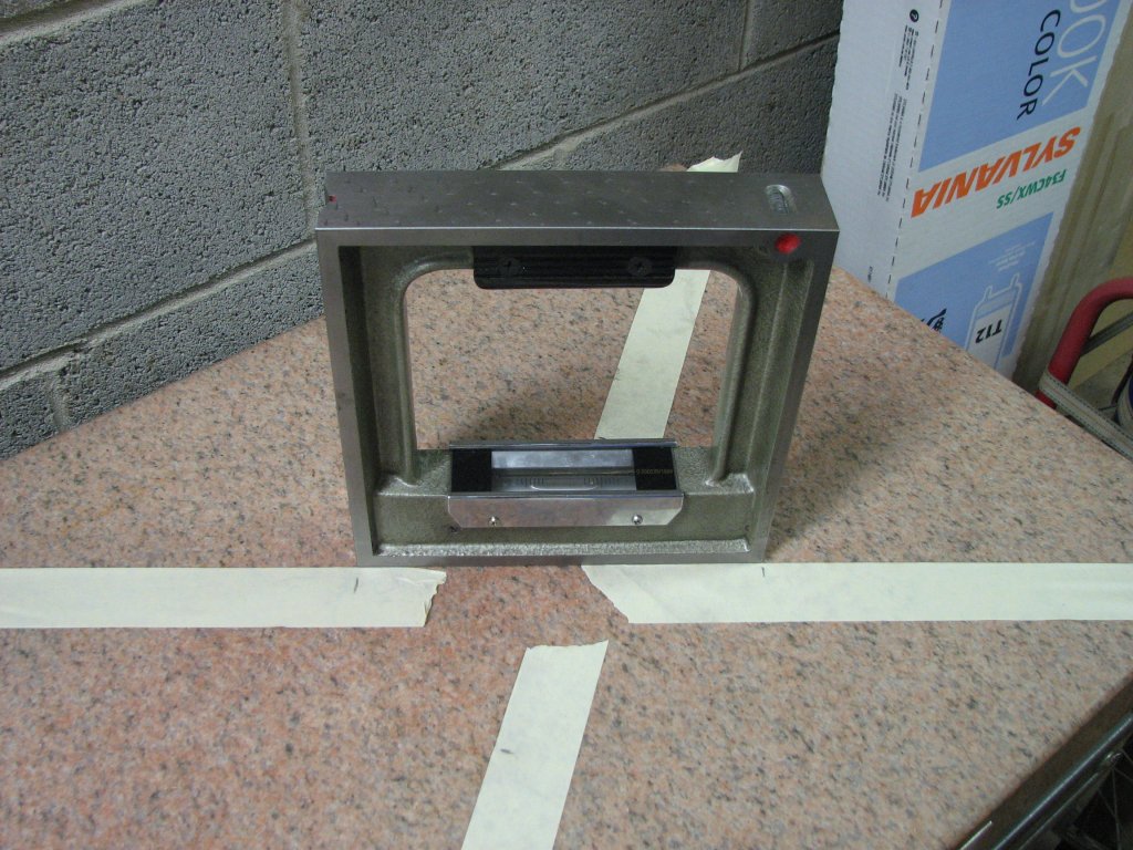
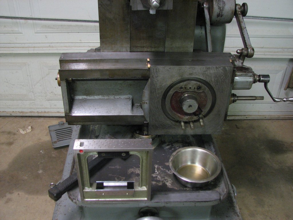
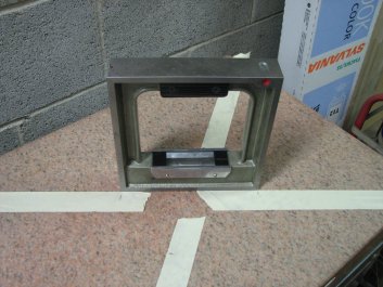
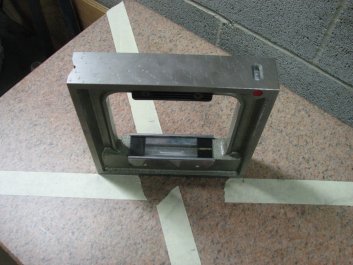
My first job was to re-level my surface plate using
my import box level. This level is graduated to
0.0002" per 10 inches of distance and is more
sensitive than my hand scraped, shop made levels
using Starrett 199 vials (0.0005" per foot
resolution). The import level is a pretty nice tool
for the money and the machining (grinding) is quite
good. The two ground surfaces (bottom and one side)
are as close to 90 degrees as I can measure on my
"A" quality surface plate using my precision box and
cylindrical squares. The only issue I have had with
this level is the adjusting mechanism. It isn't a
great design and I have had to add a flexure spring
below the vial holder to keep the adjuster and vial
holder from moving around if the level is bumped too
hard.
Before I could level the surface plate, I needed to
level the level - or at least adjust it so that it
reads the same when swapped end for end. I do this
by placing a strip of masking tape on the surface
plate and marking the position of the level. I slide
the level up against the tape and center it between
my marks. The tape helps to allow me to repeat the
level's position on the surface plate accurately. I
note the position of the bubble after the level has
sat at rest for a few minutes, then swap it end for
end and note the new bubble position after the
bubble settles. The level should read the same in
either orientation. If not, turn the adjuster and
lock it at half the difference between the two
bubble positions. Repeat this until the bubble shows
the same reading in both positions. The surface
plate does not need to be level for this to work. I
can usually get the level to read within a half of a
division of true in about 15 - 20 minutes time. Most
of the time spent is waiting for the bubble to stop
moving.

|
|
Adjusting the box level. It's a
little tricky to do because the adjustment
changes when you lock the second nut.
|
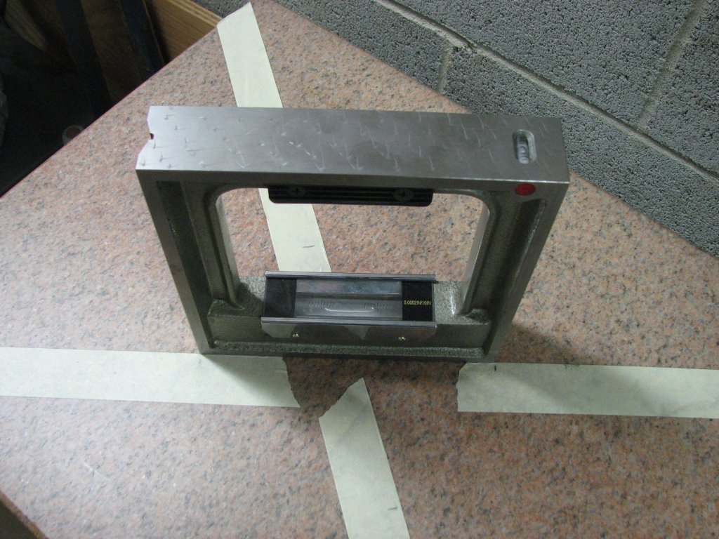
Using tape with marks to allow me
to repeat level placement accurately, I
swapped the level end for end as I made
adjustments. The level is zeroed.
|
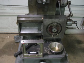
I
level
the surface plate diagonally by using two tape
stripes placed corner to corner with gaps in
the center. Again, the tape helps me to position the
level in the same spot each time as I adjust the
feet on the surface plate's stand. Once the surface
plate was level, I could now check my double-sided
straight edges and parallels for level as well as
checking them for height with a DTI. With my
measuring tools checked, it was time to try to level
the shaper again. I had run into some problems the
first time I had tried to level it. The table seemed
to slope down toward the front of the machine by
about 0.0015" over the 12" table in comparison with
the left side casting that holds the dovetails for
the ram. One or the other is out and it and I
assumed that it was the table. I figured that the
large boss was machined in the same setup as the
dovetail ways that support the ram and should be
parallel to the dovetail ways. The next issue is
that the my level shows that the cross rail is not
flat, nor is it sloped in only one direction. I get
one reading on the left, another on the right and a
third in the center. This reading is different than
the reading I get from setting the level on the top
of the saddle. To make matters more interesting, the
casting that the table support sits atop gives
another reading. The question I have is which one,
if any, are accurate and what reference surfaces do
I use to level the shaper? While it is possible to
check for square and parallel without leveling the
shaper, having the a level machine tool makes
checking it much easier for me.
|
|
The surface plate is now level
and I can check my double-sided straight
edges for being parallel with both a DTI
and a level.
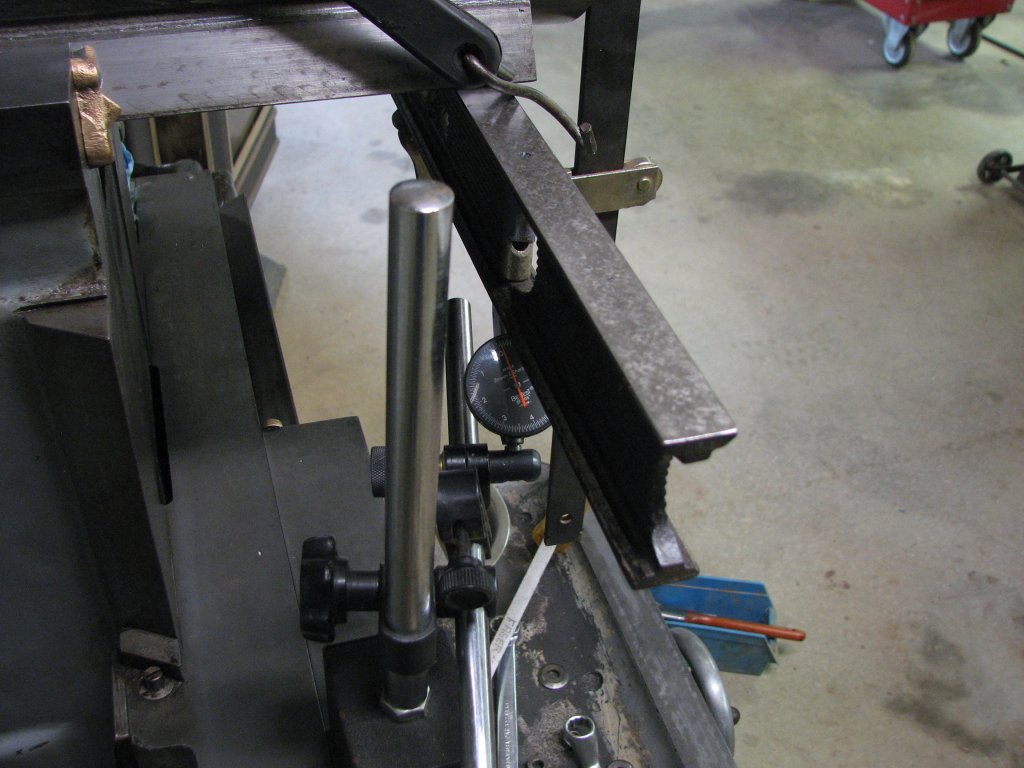
|
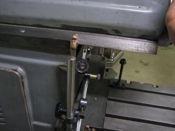
A very short pivot test with the
straight edge confirms that the top of the
cross rail casting is a bit concave. The
ways appear to be straight.
|
During my
level checks on the shaper, I removed the table. I
found a rather large burr along the top edge of
the table that mates with the front of the saddle.
I doubt that this burr was enough to account for
the difference in level I was seeing between the
table and the ram casting, but I stoned it flat to
give the table a better chance of mating
correctly. I also lightly stoned all the surfaces
I would be putting my level on.
To check why I was getting different readings as I
moved the level across the cross rail, I got out
my old Stanley cast iron carpenter's level that I
had scraped both top and bottom surfaces flat and
parallel as my third scraping project almost a
decade ago. I checked it on my surface plate and
it still is flat within a couple tenths over its
24", though being so thin, it needs to sit
untouched for a while to stabilize after receiving
the heat from my hands as I move it around. One of
these days, I will add some wood blocks to it so I
don't heed to touch the cast iron. Since the
level/straight edge is only an inch wide, it was
the perfect width to sit atop the cross rail and
not hit the ball oilers at either end. I tried a
pivot test on top of the cross rail and found that
the straight edge wanted to rotate around each
end. This indicates that the cross rail is
concave. However, the dovetail ways on the cross
rail seem to be straight.
If I place the box level on the saddle, I can run
the saddle all of the way from the left extreme to
the right and the bubble remains in the same
position, within one division. This is leading me
to the conclusion that the dovetails of the cross
rail are true, but the top of the cross rail is
not. The last check was on the machined casting at
the front of the shaper that the table support
rides on. It is obviously worn. There is some
surface damage where swarf had gotten under the
support and wore lines in the casting. The casting
is high on the left side by about 0.002" per 10"
according to my Moore and Wright level which has a
resolution of 0.0036" per 10". About a half
division out. This isn't a huge amount, but if you
were taking a cut with the feed running right to
left with the support in place, it would try to
raise the table two thousandths for each 10". The
spec for this in the Sheldon manual is one
thousandth per nine inches, so it is about twice
the allowable limit. At this point, I am thinking
that I need to scrape this part of the casting to
be parallel with the saddle top, then scrape the
bottom of the table support flat. This may change
as I still need to check the ram in both the X and
Y axis. Hopefully the X axis of the bottom of the
ram's dovetail ways will match up with the top of
the saddle. If not, I have a larger project ahead
of me.
Note: I am naming the axes as you would for a
vertical miller, which may or may not be correct.
I haven't found a source that defines it. The Z
axis is the generally the axis with the rotating
tool. Since the tool bit in a shaper is situated
vertically - although not rotating - and I am used
to thinking in terms of vertical millers, I chose
this naming: X - left right, Y - forward
back, Z - up down.

|
|
The saddle runs true across the
length of the cross rail dovetails. There
was less than one division (0.0002")
variance.
|
The boss that the table support
rides on is not in the same plane as the
saddle and is visibly worn. It will need
to be scraped.
|
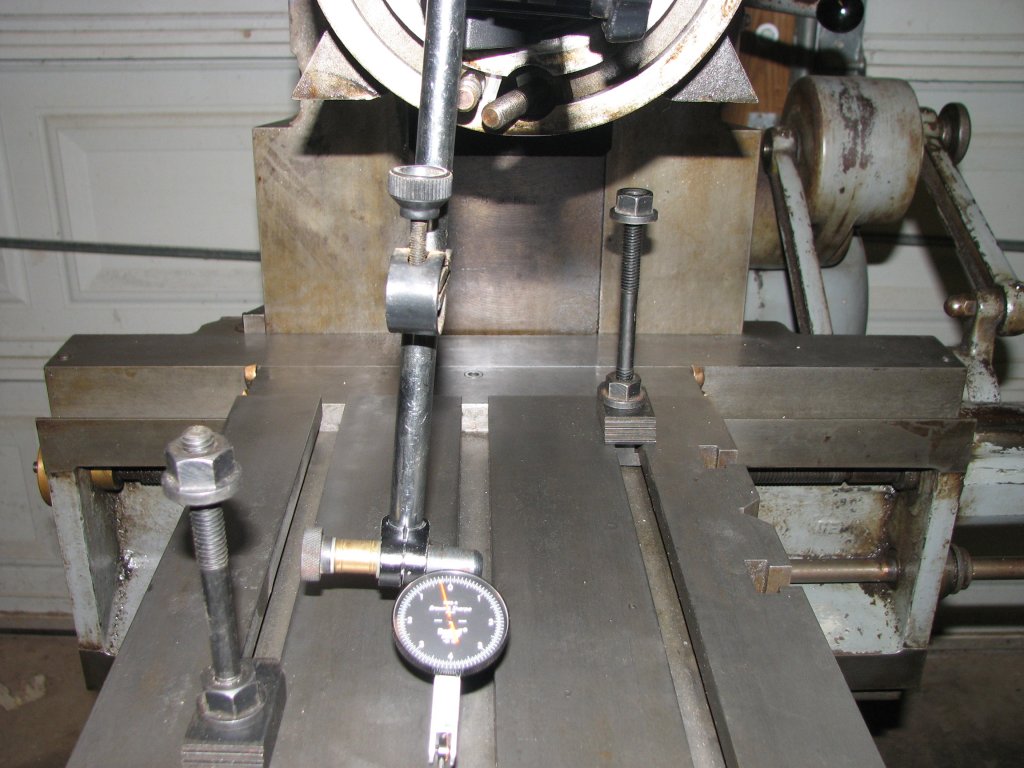
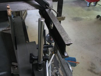
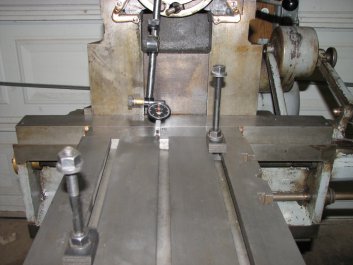
I clamped my
thin straight edge to the bottom of the ram ways.
I then set up the DTI on a magnetic base on top of
the saddle. I ran the saddle as far as I could on
each side of the clamp and read how parallel my
extension of the bottom of the ram ways was to the
top of the saddle. The top surface of the saddle
was parallel with the straight edge within two
tenths per 10" inches. The Sheldon spec
measurement is taken with the DTI attached to the
tool head and with the finger riding on the top of
the saddle. Sheldon says that the maximum
deviation should be no more than one thousandth
per nine inches. We're well within that spec. My
reason for using the straight edge attached to the
bottom of the dovetails was to extend the bottom
plane of the ram ways and compare it to the top of
the saddle. I needed to try and figure out what
references I have that can be used to level the
machine. I am now beginning to get an idea. With
my new information, I would now level the table to
be in the same plane (X axis) as the top of the
saddle.
When I had the table off, I noticed some scraping
on the mating surfaces of where the table attaches
to the front of the saddle. I don't know when this
was done, but the scraping is pretty sparse. It
looks like maybe one or two quick cycles. It
appears that someone just scraped down the high
areas and left the remainder of the mating
surfaces untouched. I have no way of knowing
whether this was done at the factory or a later
attempt to align the table. I did put a straight
edge to the table rear surface and the front face
of the saddle that it attaches to. It showed both
surfaces to have no obvious high areas. I will not
ink them up and check contact unless I have a
problem with aligning the table. I reinstalled the
table to the saddle using my engine hoist. The
table is not all that heavy, but the three bolts
that secure the table are captured in a circular T
slot and are free to move. Trying to hold the
table and line up these bolts would take more
hands than I have. Even with using the engine
hoist, it was a bit of a juggling act.
|
|
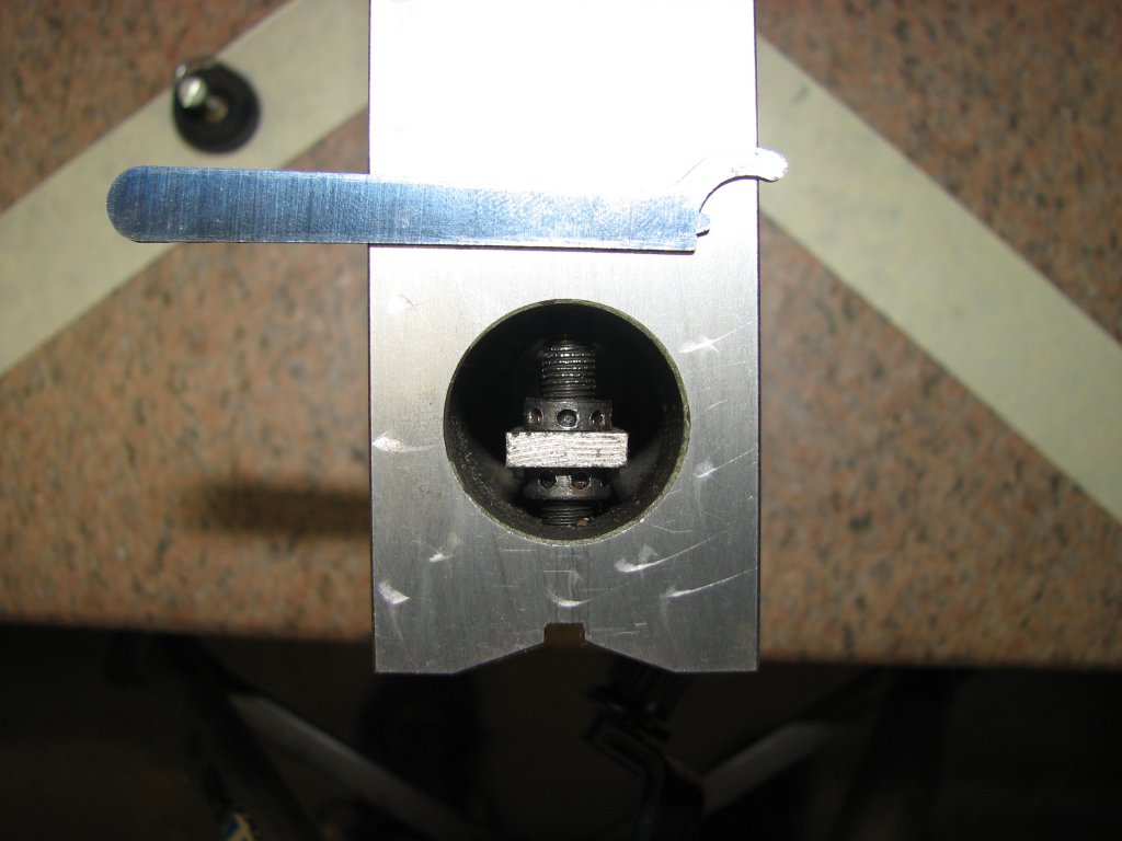
Using the straight edge to allow
me to test the planes of the bottom of the
ram dovetail ways and the saddle top for
being parallel.
|
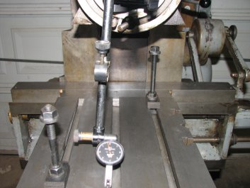
I measured the deviation from
parallel on both sides of the ram and
found it to be quite close to parallel.
It's about 0.0002" per 10" out.
|
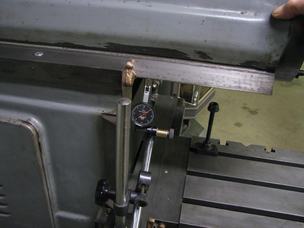
The next
check was to see if the Y axis of the table
(front to rear) was in the same plane as the
ram travel. I removed the tool head,
attached the magnetic base and set the DTI
to read the table. I set the ram travel at
its maximum of about 13.5" of travel and ran
the ram and DTI across the table by spinning
the Reeves pulley manually. I read 0.00025"
over the 12" table. The spec is 0.001" in
12". While this is very good, it has me
scratching my head. From my readings, the
ram and table are pretty much in the same
plane, but the machined casting that holds
the dovetails is in a different plane by
almost 0.002". One would think that the top
of the casting was machined on the same
setup that was used to machine the dovetails
and they should be true to each other. The
next check will be to check and adjust the
ram gib. If the gib is loose, it could allow
the front end of the ram to droop as it
extends from the shaper. If the table was
resurfaced while the ram was loose, it could
explain why the ram and machined casting
don't match.

|
|
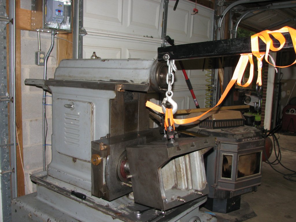
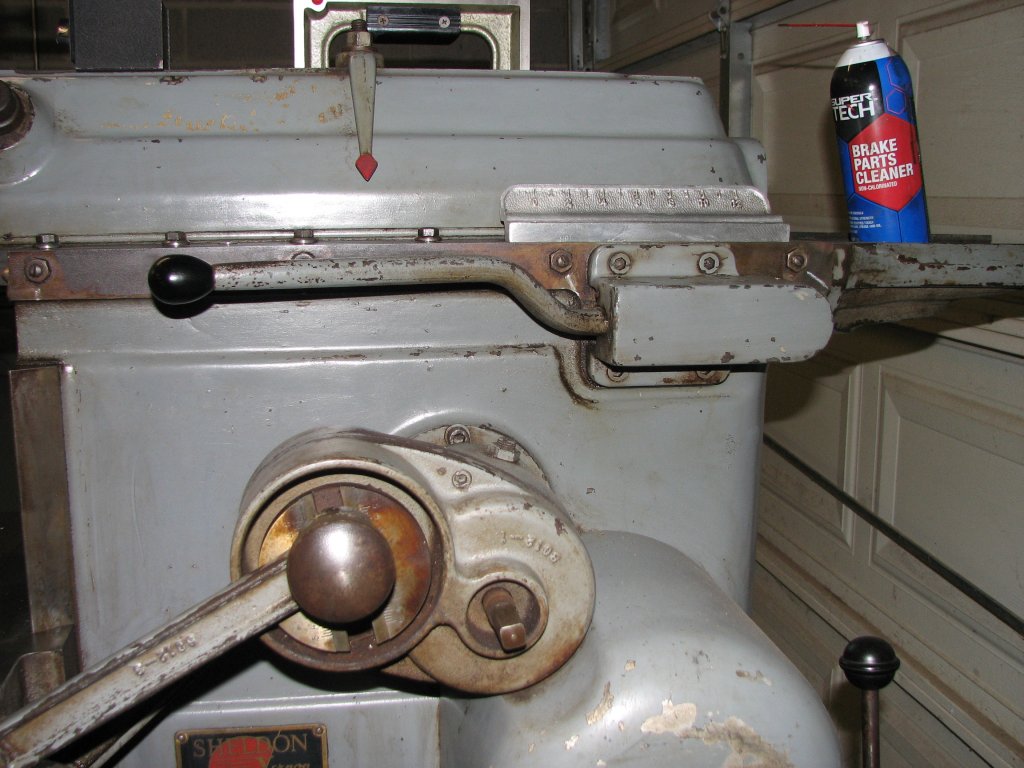
Putting the table back on so I
can check the front to rear level. The
casting is not that heavy, but getting the
bolts lined up takes 3 hands.
|
The DTI is set at the rear of the
table and the ram stroke has been set to
the maximum. The table was previously
lightly stoned.
|
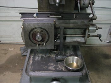
I have
been thinking about how Sheldon might have
machined this shaper for the past few weeks
and can't reconcile what I've measured to how
I think the shaper was built. I will preface
my thoughts with the fact that I don't have a
lot of experience analyzing and rebuilding
machine tools. I will also say that I enjoy
the thought process of trying to figure out
the reasons that I am seeing the lack of
parallelism between parts, but I am a bit
frustrated that the measurements don't make
sense to me. If you enlarge
the picture above left, You will see the
machined boss I am referring to. It is
machined on its top side, as well as the side
facing the camera. Inboard of the camera
facing side, it is machined again on the top
side ( a couple inches lower) to support the
bottom of the dovetailed ram and also at an
angle to mate with the angled side of the ram
dovetail. It runs from the rear of the shaper
to the front and is visibly parallel to the
ram dovetail that is extended about 4" past
the dovetailed ways that hold the cross rail.
This machined area ends at the intersection of
the front face of the dovetails that the cross
rail slides vertically on. My assumption is
that this horizontally machined area should be
square with the front face of the cross rail
dovetails and that it should also be in the
same plane as the ram dovetails. I have
measured the lack of parallelism between the
machined casting and the ram to be around
0.0015" per 10". I can only think of four
reasons why the left side ram casting is not
in the same plane as the ram.
1. I am measuring using too sensitive a level.
I could almost accept this, as the Sheldon
specs are in the realm of 0.001" per 9" for
the saddle to ram specs, or for the side of
the table to the ram plane, 0.002" per 12".
However, as you will read later, the deviation
I am seeing between the machined area and the
ram is 10 times worse than for the accuracy of
the saddle sliding across the cross rail ways
and the ram and table being parallel. In other
words, the rest of the machine is
substantially more accurate than the Sheldon
allowable limits except for this one area.
2. The ram dovetail was machined in a separate
setup than the top boss and the front face of
the casting (which are square with each
other). If the dovetails were machined in a
separate setup, I could see some miss-match of
the planes happening. However, most machines I
have dealt with or read about have a reference
boss in the same plane as the dovetails
(machined in the same setup) so that they can
be brought back to true after they wear. I
would think that this boss is the most likely
candidate for a reference.
3. The front of the dovetails have worn on the
ram and body casting and the ram has dropped a
bit in front. If this was the case, I
would think that this would mean that some
previous owner had used the shaper to
resurface its own table after the ram had
dropped. I suppose I could check for this if I
remove the ram. I would prefer not to have to
do this. -- After I adjusted the ram
gib, the ram became more parallel with the
table, so this idea probably isn't the
problem.
4. The machine tool that machined the shaper
body was out of adjustment or worn when this
shaper body casting was machined. By my
measurements, the boss plane and the ram plane
are different by a few thousandths over the
length of the ram and boss. On an industrial
machine tool of the size and rigidity
necessary to machine this fairly heavy
casting, I would expect closer tolerances.
Enough speculation. Tomorrow I will check the
adjustment of the ram gib. Depending on what I
find, I may be OK or I may end up having to
pull the ram and scrape the ram dovetails.
|

|
The DTI shows 0.00025" over 12".
Not as good as I'd like, but not too bad
at all. The table is not in the same plane
as the left side ram casting, but is close
to parallel with the ram plane.
|
Since the machined casting on the
opposite side of the ram isn't level with
the table, I will check the adjustment of
the ram gib. Chalk marks show the slotted
gib adjuster screw positions.
|
To check the
gib adjustment, I set the DTI up to read the
side to side movement of the ram and zeroed the
needle. I pushed on the ram with my full body
weight. It takes a few moments of constant
pressure to squeeze out the oil film between the
dovetails. When the
DTI's needle stopped moving, I noted the
reading. I then
reversed the direction by pulling on the ram.
Total movement was about 0.002". I don't
have any specs for the ram dovetail clearance,
but around one thousandth of an inch total
clearance is normal for milling machine table
ways I've dealt with and this was what I was
going to use. I removed the aluminum scale from
the top of the gib side casting, loosened the
top bolts that held the long gib in place, then
undid the lock nuts on the four adjusting
screws. I turned the screws in tight, the center
two first, until the ram was hard to move
by spinning the Reeves drive pulley by hand. I
backed them off a fraction and cinched down the
top bolts. This caused the ram to lock up due to
locking bolts pinching the ram gib against the
dovetail. It took a couple more tries until I
had reduced the side to side play to 0.001". I
re-ran the test of checking the parallelism
between the ram and table. The amount the ram
was off being parallel with the table was now
down to about 0.0001" along the 12" table, with
the front of the table being lower than the
rear. This is an order of magnitude better than
the Sheldon spec limit of 0.001" in 12" and
better than my previous measurement of 0.00025".
Perhaps I
will never know the reason for the boss along
the left side dovetails not being parallel
with the ram. At this point, it doesn't really
matter. The ram and table are in the same
plane and the X axis is square with the ram
stroke. I suppose that I could scrape the boss
to be co-planar with the ram and saddle top,
but since I now know that the table is true to
the ram and the saddle, I am satisfied that I
can level the shaper by the table. I had
considered planing the table before, but there
is no reason to do this when I am only
measuring one ten-thousandth difference over
the length of the 12" table. I will still
scrape the machined portion of the casting
that the table support rides upon so that it
is true with the side to side saddle axis and
get on with machining the vise rails. Getting
the table support flat and true should help
the shaper make parts that are square with
themselves.
|

|
With the DTI set to measure side
to side movement of the ram, I pushed on
the ram to squeeze out any oil film.
Reading of - 0.001"
|
I now pulled on the ram long
enough to displace the way oil in
the other direction. This time the reading
was + 0.001". Total of 0.002" movement.
|
That's it
for this installment. The next steps are to work
on the tool head and to scrape the table support
pieces.