
|
| HOME What's New
Workshop Stuff South Bend 405 Lathe Bench Grizzly G3103 Mill Bringing Home a
Sheldon 12" Shaper
|

Way Alignment
Tool
May 21, 2016
Back in 2010
when I was getting ready to scrape my import mill, I made a crude
approximation of the King Way alignment tool. It used flat stock
for the horizontal bar and only used a one vial 6" level that I
had made using some cast iron and a Starrett 199 - 0.0005" per 12"
resolution spirit vial. Around the same time, I also made a cross check level
using two of the Starrett vials, but there was no easy way to
attach it to the flat bar of the makeshift alignment tool. The
tool helped with scraping in the mill, but I realized that I
needed to make another one that was a little closer to the
original King Way design. I shelved the project for another day.
Six years later, that day has come. I have a scraping project
coming up where a proper dovetail way alignment tool would be a
big help.
Over the years,
I have read a lot about the King Way alignment tool and have
collected pictures of the King Way and some shop made copies. The
tool is ingenuously simple. It uses a horizontal bar to hold the
cross check level, two vertical bars to hold a ground sphere on
one side and a tube with a slot on the other, and an arm to mount
a dial test indicator (DTI). In use, the tube with the slot is
placed on the dovetail or V ways, the ball has a ground ring
placed beneath it and is positioned on the opposite ways. The
cross check level is then set to level in both planes and the DTI
is placed in contact with the way you want to measure for height
or divergence from parallel. By sliding the tool along the ways,
you get your readings.
 |
 |
|
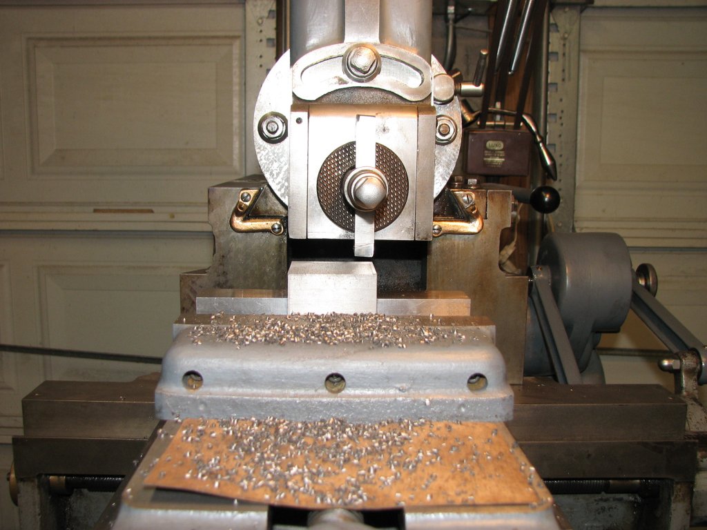
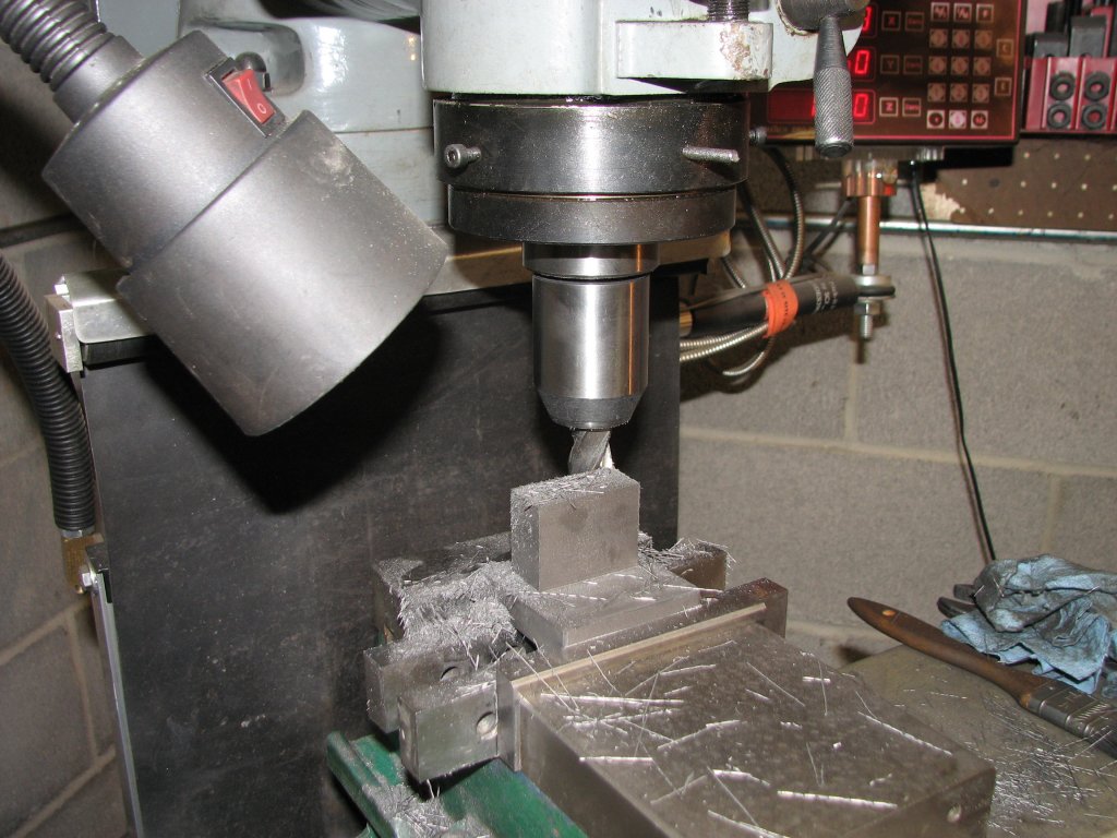
Squaring up some cast iron blocks. |
Cutting
out some sections to save milling time. |
I started the
project by squaring up some cast iron blocks on the shaper. I then
cut and milled the blocks so that holes could be bored at 90° to
each other. The holes were reamed to 0.501" diameter and then a
slot was milled with a slitting saw so that the 1/2" diameter
ground bars could be clamped in the holders.
 |
 |
|
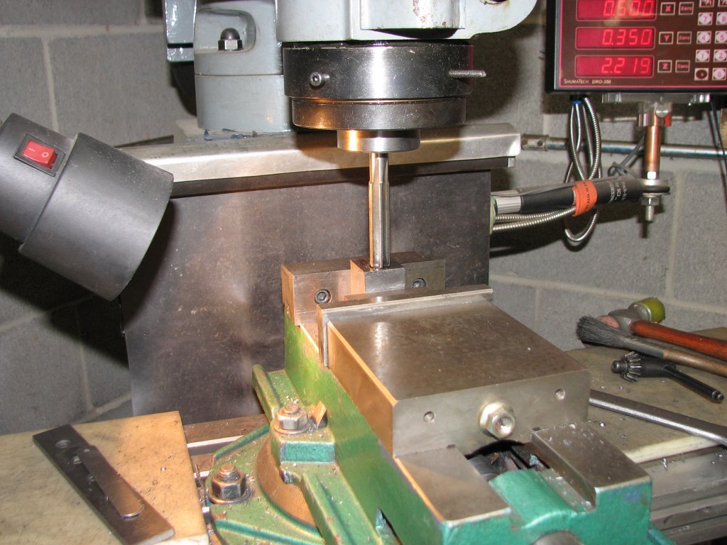
Reaming the holes to 0.501". |
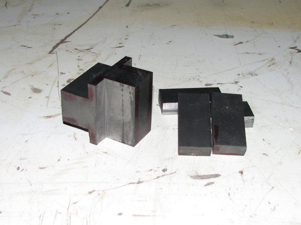
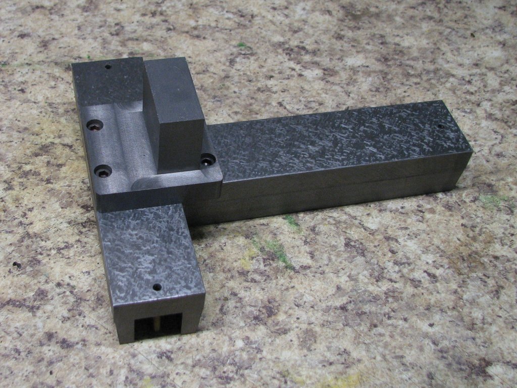
Progress
so far. |
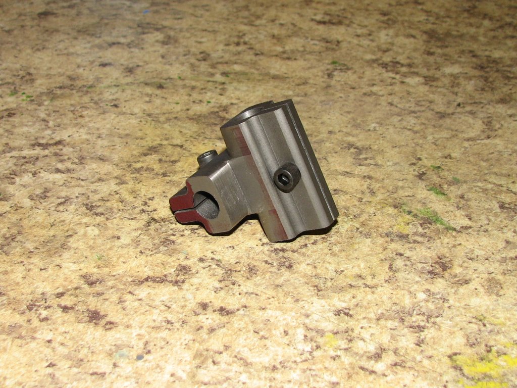
The shape of
each holder was refined a bit and threads were tapped so that the
clamp could be tightened on the bar. If I had to do the job again,
I would change the design of the two bar mounts so that the
mounting point of the horizontal bar would be at the top of the
mount that supports the vertical bar. This would have allowed me
to make the level holder a bit shorter.
 |
 |
|
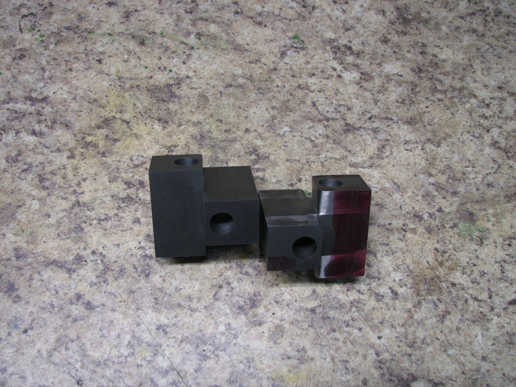
Refining the shape. |
A
little more progress |
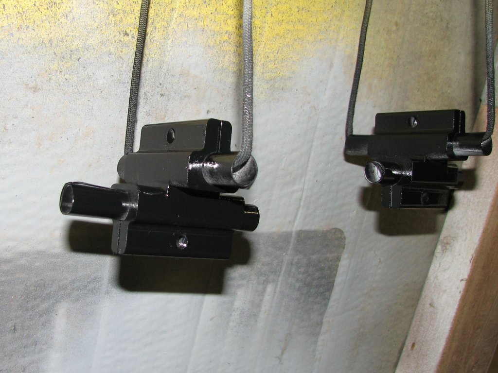
When the holders
were finished, I gave them a couple coats of paint using rolled up
paper to keep the paint out of the reamed holes.
 |
 |
| Time
for some paint. |
Test
fitting the tool on the lathe. |
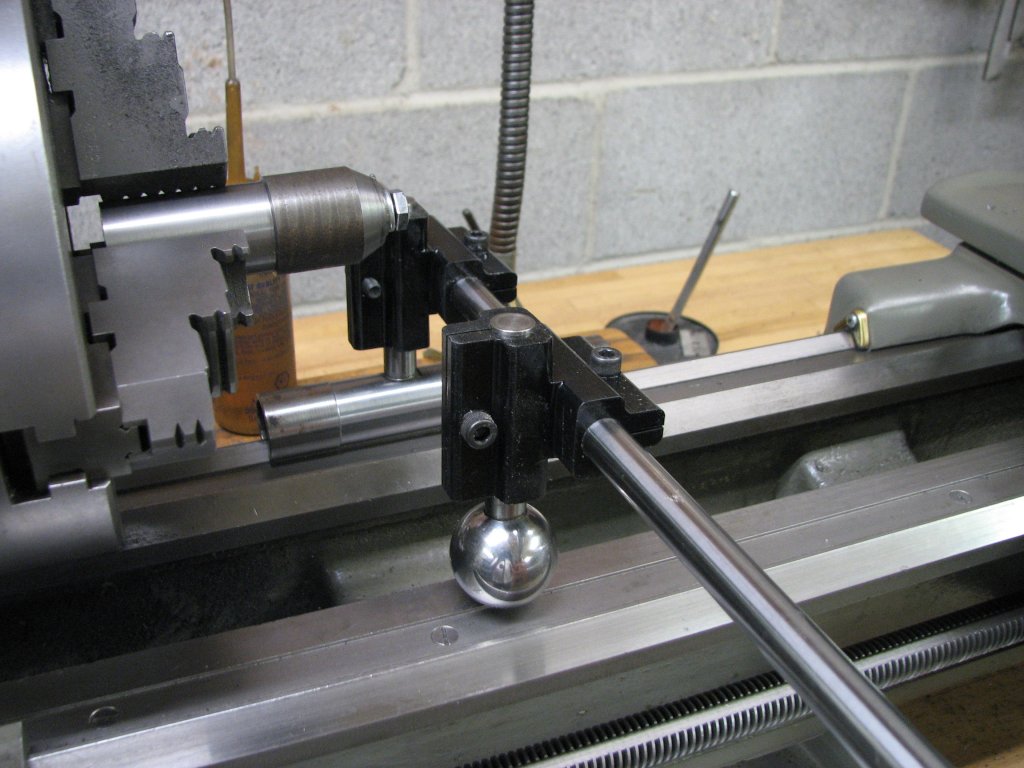
With the two
holders completed, I set the tool up on my lathe so I could
measure how wide the holder for the cross check level could be.
While I wanted to be able to set up the tool on the tailstock ways
of my small South Bend lathe, the closest I could get the upright
bars with the level between them was about 3.5". The distance
between the two inner ways of the SB are about 3.0" center to
center. This means that I will have to mount the level to the
outside of the uprights when working on the tailstock ways. I
could have narrowed the level holder clamp, but I was concerned
that the weight of the level would rotate on the horizontal bar.
The original King Way tool gets around this by slotting the
horizontal bar and using a thumb screw for the level holder that
locates in the slot. I am using two screws to clamp the holder to
the bar. So far, it seems to work well.
 |
 |
| I need
to measure the distance between the holders and how much
clearance I have for the cross check level. |
Rough
milling the holder that will attach the cross check level
to the horizontal bar. |
When I made the
cross check level, it was machined from a round of cast iron. It
is 6" x 7.5" x 1.25" thick and it is pretty heavy. I was worried
that if the T shaped leg of the level was centered on the
horizontal bar and I used a short tube when testing bed ways, the
whole tool would tip toward the leg on the long side of the level.
My solution was to make the level holder able to be reversed and
thus get the bar clamp closer to the balance point of the level.
This worked out very well and even with the short 5.5" slotted
tube, the alignment tool doesn't want to tip when I tried it on
the lathe.
The level used
on the King Way tool looks to weigh less than mine. From what I
understand, it also uses 0.0003" per 12" vials. The bar clamp
appears to be cast into the level base rather than being an add-on
piece like my copy.
 |
 |
| Test
fitting the holder to the level. The level overhangs the
holder by a lot on the right side. |
I made
the holder so it could be reversed. This moves the balance
point a bit to the right. |
Once I had the
level holder machined and I was able to make sure that it was
square with the level, I drilled and reamed a 0.501" hole for the
cross bar. I then machined a slit so that the holder could be
clamped to the bar. Last, I refined the shape of the holder and
added a couple pockets in the sides so that the vertical bars of
the tool could be moved closer together. The upright bars can be
adjusted to accommodate ways from about 3.5" to 15" apart with the
current horizontal bar while holding the level between the
uprights. For checking ways that are closer together than 3.5",
the level can be moved to sit outside the uprights.
 |
 |
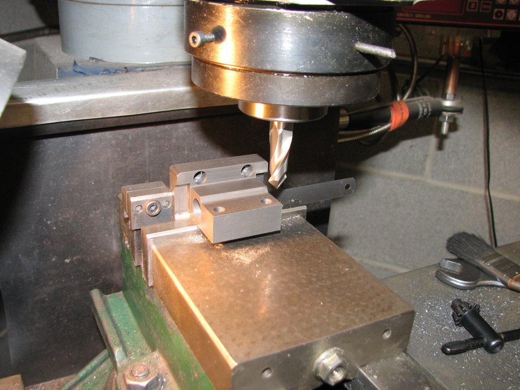
| Finish
milling the holder. I also milled some pockets so that the
two legs of the tool could slide closer together. |
Checking
to see how everything fits. I need longer vertical legs.
This will help with the DTI arm placement. |
When I built the
cross check level, I ended up making typical vial adjusters after
a couple of unsuccessful designs. I ended up with coarser threads
than are generally used for this purpose. My last design used 8-32
studs and cone shaped nuts that fit into reamed and slightly
beveled holes on the vial holder end caps. To raise one side of
the vial, you loosen the top nut, then raise the lower nut, then
lock the top nut back down. This was a little fiddly because the
8-32 threads lift and lower the vial more than the resolution of
the vials with barely a fraction of a turn. It took some of time
to get the level adjusted, but once it was adjusted, it seemed to
stay put pretty well. After more than a year of storage, the
bubbles still centered perfectly. Now that I was using the level
on the alignment tool, I needed to be able to re-level the vials
with each use of the tool. I also wanted the ability to adjust the
vials more finely. To do this, I decided on using a differential
screw adjuster on one side of the vial holder. I had a spare
brass end cap I had made when I built the brass vial holders. For
a proof of concept, I tapped this end cap for 1/4"-20 threads. For
the adjuster, I used a 1/4"-20 bolt with 8-32 internal threads
tapped in to fit on to the 8-32 studs. This allowed me to raise or
lower one end the vial holder by 0.01875" per revolution of the
bolt. Not a fine enough adjustment for the sensitivity of the
0.0005" per 12" resolution vials, but better than the 8-32 threads
alone. The test worked out very well. I found that I could adjust
the vial pretty easily.
To make the permanent adjusters, I ordered some 1/4"-28 threaded studs and a 1/4"-28 tap. The closer the thread count of the differential screws are to each other, the finer the adjustment. The 1/4"-28 and the internal 8-32 threads would give me 0.0045" height adjustment for every revolution of the adjuster. A tenth of a revolution on the adjuster would raise or lower the vial holder by about half a thousandth. Not a super-fine adjustment, but it should be sufficient. I turned and knurled some adjustment thumb screws from brass to top off the adjustment screws. To get both gross and fine adjustments, I turned an 8-32 adjuster for one side of the vial and use the differential screw on the other. One side for gross adjustment and the other side for fine adjustment. Though they're not shown in the picture below right, I ended up putting springs under each side of the vial holder end caps to help hold the vials to their adjustment. I have to say that the adjusters turned out to work as well as I had hoped they would. It is very easy to get the level into adjustment as long as I have the cross bar somewhat level.
 |
 |
| Proof
of concept for the differential adjustment screw. The
1/4"-20 thread will be changed to 1/4"-28 for the finished
adjusters. |
With
the adjuster knobs made. I again set it up on the lathe to
check its operation. I need to make a new slotted tube to
fit the lathe's ways better. |
I made up a new
slotted tube from the only appropriately sized stock I had on
hand, 1" schedule 40 steel pipe. I need to purchase some tube with
a 1/4" wall thickness to make the proper part, but decided that
making a slotted tube from the schedule 40 pipe would give me a
chance to play with the tool and get some practice using it. I
also need to find my shop made tool post grinder to grind the end
diameters of the next tube I make. I haven't come across it since
we moved into the new house and shop, but I still haven't unpacked
all of the boxes yet.
 |
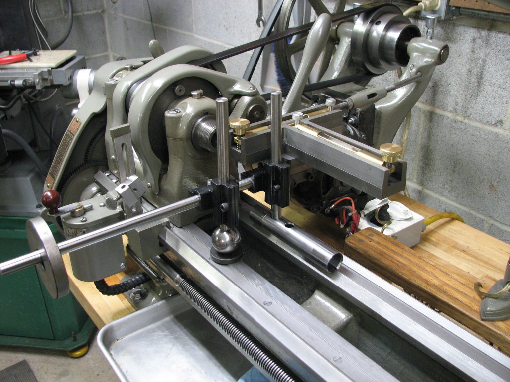 |
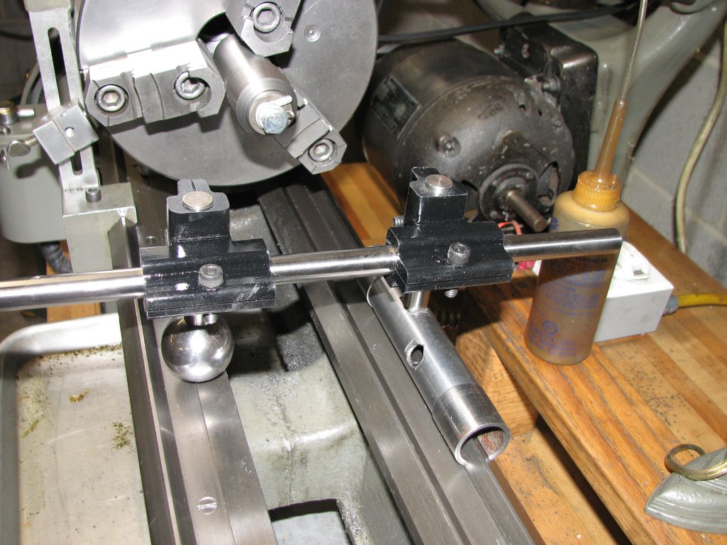
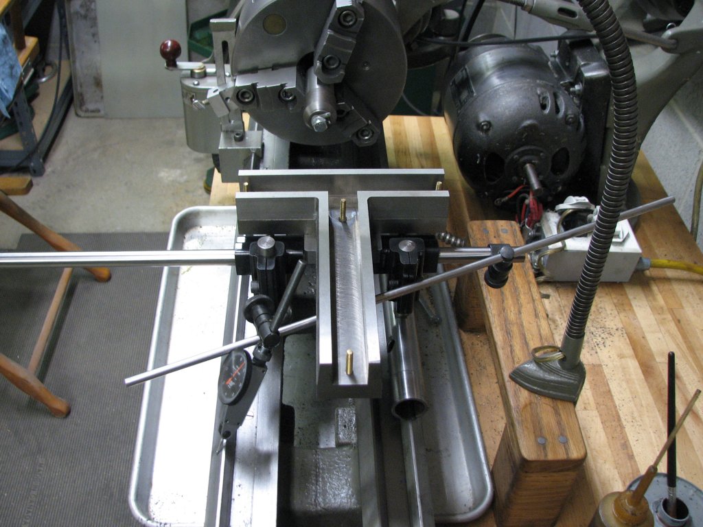
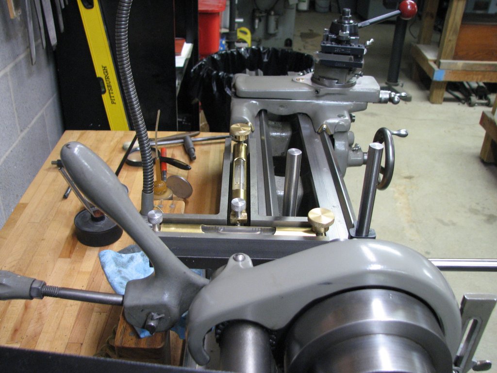
| With
the level mounted outside the uprights, I am setting the
vials to be level. |
Due to
the weight of the level, I needed to hang a little ballast
on the horizontal bar to prevent the tool from tipping. |
In the last two
pictures, the new slotted tube has been machined. The center
section of the slot in the tube has been relieved so that only the
1" sections at each end contact the ways. To get the mating
surfaces of the ends of the tubes square with the ways, I put a
coat of ink from a felt tipped marker on the four flats, then
rubbed the tube against both some V and dovetail ways. I used a
fine file on the area where the ink had been rubbed off until I
had four surfaces that contacted flush with the ways. The process
was very similar to scraping flat surfaces, only I used a file
instead of a scraper. Before I aligned the tube's slot, I tapped
four holes into the tube. Two for V ways and two for dovetail.
Because the pipe is so thin, I didn't get much thread engagement
for the 1/2"-13 threads I turned on the ground 1/2" O1 stock , but
it will have to do until I get the proper thick walled tube. The
extra hole for each position will allow me some choice in
positioning the slotted tube to see what works best.
With the tool
more or less complete, I set it up on my SB9 lathe to test it out.
Since the tailstock ways on the workshop lathe are only about 3"
apart, I needed to move the level to outside the uprights. Since
this puts the weight of the level to one side, I needed to
counter-weight the horizontal bar to keep the tool from tipping.
Not the best procedure, but it seems to work OK.
For my test of
the new tool, I will attempt to measure the wear of the saddle
ways on my lathe. It should be good practice for the upcoming
project. To make sure that I am getting true readings, I will
first check and correct for any twist in the lathe bed. The
tailstock ways are realatively unworn. The scraping that was done
at the factory to dust off the planer marks when the ways were
machined are still evident, so using the tailstock ways to check
for twist should be pretty accurate. In the past, I have attempted
to correct for any twist by turning collars on a long piece of
stock, then shim the lathe bed until I was able to turn the
collars to pretty close to the same diameter. I currently have a
0.002" shim on the operator's side of the lathe bed foot at the
tailstock end. However, as some sage person once said, "Machine
tools are made of rubber." Add the fact that this light lathe is
mounted to a butcher block bench and there is no doubt that the
twist of the bed could change with the seasons. I am looking
forward to seeing how close I can get the lathe to being free of
twist and then checking the lathe for wear.
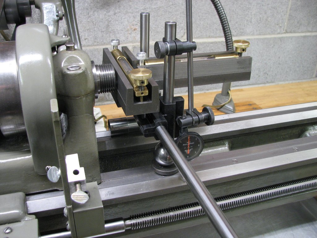
Using the setup
shown in the last two pictures, using no DTI and just reading the
level bubbles, I checked the tailstock ways for twist. The
readings I got made me scratch my head. With both vial bubbles
centered at the headstock end, I moved the tool to the right about
six inches. The bubble measuring the X axis, the direction that
the top slide moves, showed three increments high on the flat way
side. I slid it toward the tailstock another six inches. It was
now showing two increments high. At the third six inch stop, or
18" from the headstock, the bubble was centered again. The vial
for the Z axis, left to right along the ways, showed the bubble
pretty close to centered at each stop. I set up the DTI to measure
the outer angled flat of the front V way and repeated the test.
The V way showed less than 0.0003" deviation over the 18". It
showed a little wear about 6" from the spindle snout and 0 in
front of the snout and after about 12" from the snout.
Apparently I
have a hump in the ways closest to the operator. Three divisions
of the Starrett 199 vials would be 0.0015" per 12". That seemed
like a lot. I quit for the night and decided to give it some more
thought. The next day, I repeated the test with the same results
and then it dawned on me that I was using vials calibrated to
measure 12" and I was actually measuring the rate of slope for
ways 3" apart. Duh. So the hump is there, but it's not 0.0015",
it's closer to 0.00035". To confirm my thoughts, I re-leveled my
surface plate using my frame level (0.0002" per 10") and used a
0.100" and a 0.10025" gauge block under my best wide parallel with
the frame level above it. The results from placing the gauge
blocks 12" apart and 3" apart and measuring their respective
slopes confirmed my thoughts. Sometimes I need to spend the extra
time to confirm what I think I know.
I will have to
remember that the distance between the slotted tube and the sphere
determines the amount of rise or fall that is depicted by each
increment on the spirit vial. As for the South Bend, while I would
prefer no hump in the ways, 3 1/2 ten-thousandths is a lot better
than a thousandth and a half. I doubt that I will do anything to
try and correct this. I have learned to produce pretty accurate
work on this lathe in spite any deficiencies it may have.
Knowing where it is inaccurate will help me to produce better
work.
I have a couple
old lathe beds that I will spend some time mapping out. I need
some practice time with this tool before I start using it to help
me scrape ways that are true.
© Fager May 21, 2016