While I
pondered how to keep the bearings clean, I was also looking for proper
replacement bearings and maybe a new or used spindle - if one happened
to show itself. I put up some ads on a couple of bulletin boards
I frequent and sent email off to a dozen or so spindle
rebuilders. I didn't have much luck finding a replacement
spindle. The rebuilders wanted to rebuild mine and the prices
were a bit more than I was prepared to spend at this point.
|
|
Angular
Contact Bearing - back to back configuration
|
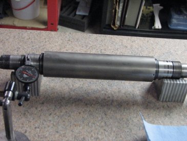
Spindle
drawing - measurements and layout
|
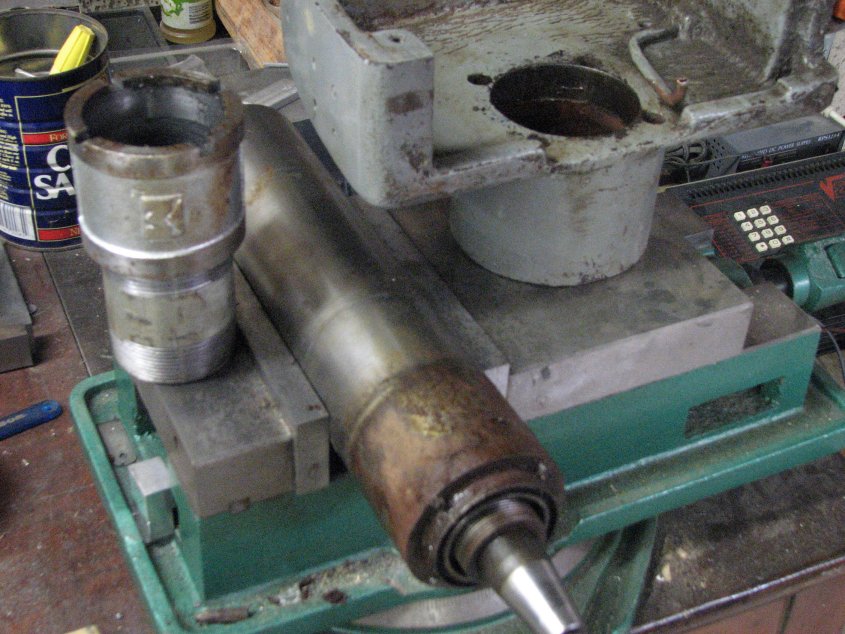
Before I could look for
bearings, I needed to pull the spindle apart and find out the quantity
and size(s) I needed. During my reading, I did find out that I
needed to pay close attention to how the bearings came out so I would
know how to reinstall them. Angular contact bearings can be
arranged in a few different configurations depending on what the
manufacturer had in mind. The configuration is first dependent on
how many bearings are needed to support the spindle shaft and then
dependent on how much and in which direction the forces will be applied
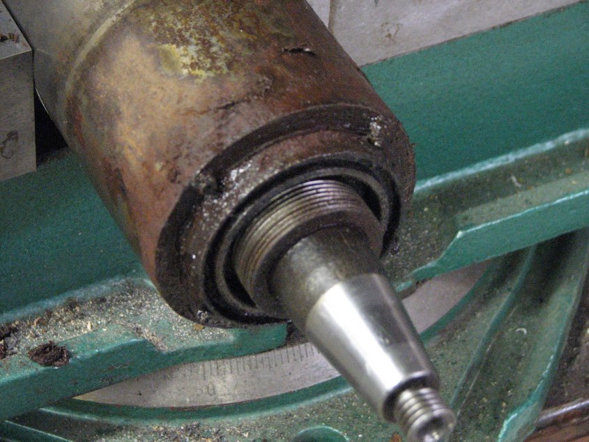
to the spindle. When I finally got the spindle apart, I found a
total of 4 Barden 107 matched angular contact bearings (two on each
end) in back to back configuration. Back to back in Barden's
symbols is shown as / \. Each slash indicates the axis of the
balls when viewed from the side and the ball at the top of the
bearing. Each pair of bearings have the printed sides touching as
shown in the image above. Other possible configurations are face
to face ( \ / ) and face to back ( / / ). On the back end
of the
spindle, both the face to face and back to back configurations would
have the bearings in the same configuration as on the front of the
spindle. For a spindle with face to back on the front, the rear would
be the opposite, or back to face. This configuration preloads
the bearings as two front against the two rear( // ----- \\ ), rather
than the more
common preload of 1 against 1 in the front and 1 against 1 in the
rear ( / \ ----- / \ ). From my limited experience in mills,
lathes and grinders, I
have seen back to back used most often.
|
|
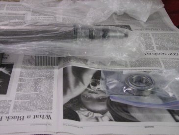
Cleaned and bagged - just like a
small clean room
|
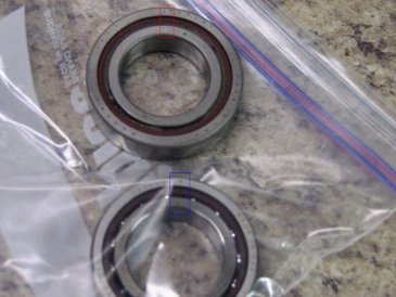
Red/blue boxes show high run out
marks on old/new bearing. Set marks 180° from spindle high marks
|
I had been
watching Ebay, among other sites, for Barden 107 bearings. I had
found a cross-reference
for bearings that showed that Barden's 107 number matched a few other
manufacturers 7007 numbers. I set up automatic searches for those
numbers also. The letters and numbers after the size designators
include nomenclature for a matched pair of bearings, whether they were
duplexed and whether the duplexing was face to face, back to back, or
whatever. The letters and numbers also depict whether or not the
bearings are marked for radial run out and how much maximum run
out. These numbers are not etched on the Barden bearing
shell. They are found only on the sticker that comes on or in the
box. On the second day I checked for Barden 107* on Ebay, I found
my bearings. The seller only had one pair listed, but when I
wrote him with a ton of questions, he graciously answered my questions
and said he had another pair as well. I ended up with 2 pair of
107HDL with codes for duplex back to back, light preload, I.R.
radial run out 0.00005 max. There's a good page with the Barden
nomenclature here.
The nicest part of the purchase is that 2 pair cost me less than 1/2
pair would have cost retail. Sometimes I get lucky.
While I waited for the bearings to arrive, I set out to find some
bearing grease. I had learned that one doesn't use unfiltered
grease in a bearing with these close tolerances. Just like the
bearings, the grease is special. The recommended grease for my
application was Kluber Isoflex NBU-15. It was a bit of a search
to find it. McMaster has something close, but not quite as good
for my application and the smallest size was a lot more than I
needed. Barden recommends only 2 cc of grease per each 107
bearing and too much grease can cause the bearings to overheat. I
finally found 30cc syringes of the Kluber from Precision Spindle.
I gave them a call on a Monday and had the grease on Wednesday.
Fast service.
With all of the individual parts cleaned and bagged, I pulled the
bearings out of their packaging while my freshly gloved hands, a couple
of new zip-close bags, some lint-free wipes and the grease syringe were
all inside a large clear plastic bag. This was my clean
room. With the clear bag surrounding everything, I was able to
inject the 2 ccs of Kluber grease in each of the bearings and work it
around, then put each pair of bearings in the small zip bags. The
only dust that the bearings may have seen would have to have come in
when I carefully opened it to add the bags, grease, etc. It's
still not as good as having a clean room, but it was a heck of a lot
cheaper.
|
|
Making sure that the spindle
wasn't bent
|
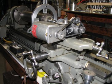
Shop made tool post grinder (TPG)
|
|

|
Checking for concentricity of the
taper
|
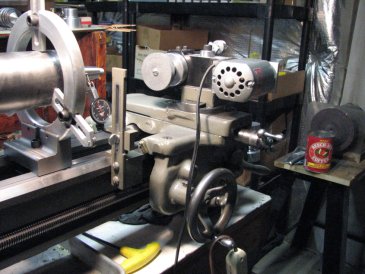
Checking the temps as run-in was
done on lathe
|
Once the
bearings were greased, I removed my wrapped spindle from the freezer
and tried to slide the warmed front bearings over the
journal. They were a little too tight for this to work, but
I was ready for this possibility. I moved the bag, with spindle
and one pair of bearings inside, to the cleaned and waiting hydraulic
press. Everything was already set up for this press job.
With the bag still surrounding the spindle and bearings, I pressed the
front bearings home with a press-tool on the inner race. I didn't
even tear the bag. Still working in the bag, I moved in the
clean spindle housing from another bag. Back to the press.
This time the press-tool pressed on the outer race to seat the bearing
and spindle shaft into the housing. Next, I added the front
spacers and end cap and cinched them down finger tight. The last
job on the press was the one I was most concerned about. I needed
to press the pair of rear bearings on to the spindle shaft and into the
housing at the same time. Fortunately I had already made sure
that the inner press tool was able to nest inside of the outer press
tool, and so put equal pressure on both races. This required
using a shim on the outer race for the first bearing, then removing it
for the second bearing. These bearings are NOT an interference
fit, just a very close sliding fit, so there was very little actual
pressure being used. Once the rear bearings were close to their
intended location, I added the cleaned spacer, nut and end cap.
With the inside of the housing now closed off from the outside and
little possibility of dust entering near the bearings, I was able to
tighten down the end caps. Tightening the end caps sets the
preload. There's no measuring torque or any computing done at
this stage. As long as the new bearings measured the same as the
old ones in thickness and they had the same preload rating (both old
and new were "15° - light preload"), then the preload setting
machined into the bearings would automatically be correct. I had
measured everything before I began the assembly and it all looked
right, but it was reassuring that when the nuts and end caps were
tightened, there was no end play in the shaft and just a small amount
of drag when the shaft was turned in the housing.
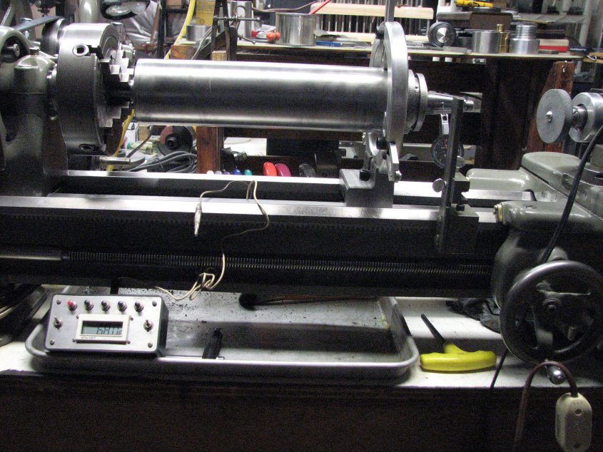
I chucked up the spindle in a 4-jaw on the lathe and used a steady rest
with the fingers reversed to hold the housing. Starting in back
gear at the lowest RPM, I ran the spindle while checking the
temperature of the housing above each pair of bearings. When I
finally got up to around 1000 RPM and let it run, the front bearings
were reading about 92° and the rear about 90° at the 15 minute
mark and had dropped to about 80° by the end of an hour. I
had looked for specs for bearing temperatures, but didn't find much
more than "The bearings shouldn't run hot." Since the spindle
normally spins at 3000+ RPM, they might have run hot if I would have
spun it up to high speed in the beginning, but by running it in slowly,
I was able to avoid that issue.
I let the spindle run for another hour. By this time, the housing
temperature was just a few degrees over the ambient room temperature of
74° at 1000 RPM. The next step was to grind the spindle
taper. I had built a quick and dirty tool post grinder as an
early project to grind an inside taper on a end mill grinding
jig. I didn't use angular contact bearings, but did preload the
bearings a bit to lessen the end play. I doubt that these
bearings will last too long, as they were not meant for this type of
service, but it was better than using a Dremel as a TPG.
I dressed a 3" wheel, set the compound slide to a little over 7°
and made a very light grind with the lathe turning the spindle at about
350 RPM. I checked the angle with some Prussian blue and an
almost new Sopko adapter. It took a couple trys to get the angle
correct, but once I had the angle right, I ground about 3 thousandths
off of the taper. The diameter of the spindle shaft is 1.0625"
just inboard of the taper, so the 200 series adapter, with its 1.000"
maximum inside diameter doesn't seat all the way down on the
taper. This is nice as I could regrind the taper many times
without running out of real estate.
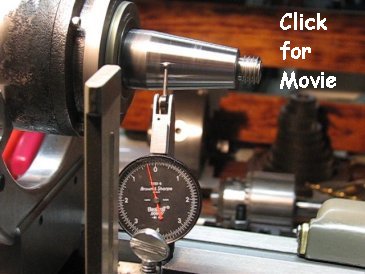
So how did it turn out? I'm so amazed at the job this tool post
grinder did, that I had to shoot a short clip of the outcome.
There is just a hint of a waver from the needle on an indicator that is
graduated in 50-millionths of an inch (half-tenth). Not too
shabby.
|
A
little out of focus at start, but almost zero run-out
|
The finish
on the taper could have been nicer with a better grinder or maybe with
a better choice of wheel, but it is so much better than the 0.0012" run
out I started with, that I'm quite happy with the results. I got
so excited with the results, that I went ahead and reinstalled the
spindle in the grinder that evening. I paid for this the next
day, as I didn't get to bed until almost midnight on a Sunday night
with a very early alarm (4:30 AM) on Monday morning. I told
myself that I wouldn't have been able to fall asleep anyway, due to thinking about it.
For the last week or so, I have been doing lots of grinding. On
most things, the finish I'm able to get is very nice. On others,
I find that I have lots to learn. However, any finish problems
I've had can't be blamed on the spindle taper not being true - and
that's a good thing! I reground the table, the chuck, some long
thin stock for practice and I am now working on some fixtures to assist
me in grinding some templates so I can do a good job of scraping in a
fairly "new to me" South Bend model A saddle and cross-slide I added to
convert my 405 "C-type" lathe to a "B-type" lathe. They were not
very worn and the saddle checked favorably against my very slightly
worn South Bend 405 bed ways, but I have been wanting to "do the job
right" and scrape the saddle ways to a perfect fit. Since I
needed to remove the saddle in order to clean the grinding dust from
the lathe anyway, now would be a great time to scrape it in. Yes,
I threw a towel over the lathe while grinding, but I know that the
grinding dust still gets through. The dust settles on surfaces
all over the basement and gets kicked up for a while after a grinding
job. This is one of the reasons why the surface grinder lives in
the garage - away from the rest of the machine tools. Well, that
and because it was too much work to move it to the basement.... but
that's another story.
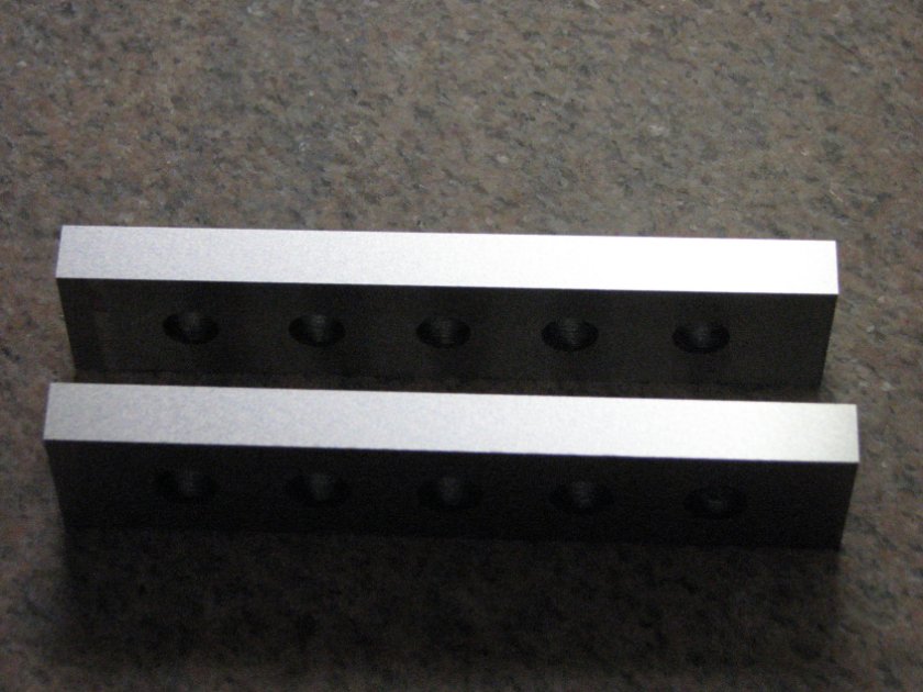
Here's a parting shot of a pair of
parallels that I ground after the spindle repair. Not too bad
of a finish for a novice..


