HOME
What's New


Workshop Stuff

Workshop

Moving the mill

Spindle Noises

ShumaTech Digital Readout

ShumaTech DRO Continued

ShumaTech
DRO-350 Repairs


South Bend 9" Lathe

South Bend 405 Lathe Bench

Grizzly Mill Revisited

Surface Grinder Rebuild

Surface Grinder Continued

Grinder April 6, 2008

Grinder April 20, 2008

Grinder August, 2008

Grinder September, 2008

Grinder November, 2008

Grizzly G3103 Mill
Rebuild

Grizzly G3103 Mill
Rebuild - Part 2

Moving the Shop

Moving the Shop 2

Bringing Home a Sheldon 12" Shaper

Sheldon 12" Shaper 2

Sheldon 12" Shaper 3

Sheldon 12" Shaper 4

Sheldon 12" Shaper 5

Sheldon 12" Shaper 6

Sheldon 12" Shaper 7

Sheldon 12" Shaper 8

Sheldon 12" Shaper 9

Way Alignment Tool


Email Jim


 workshop.gif
DoAll D624-8 Surface Grinder Continued
Weekly Updates

Week of April 6, 2008
This week started off with working on the cast iron straightedge.  Since the surface that I chose to scrape was in fairly good shape to begin with, progress has been quicker than scraping the ways of the surface grinder's table.  The one toughest thing I have encountered on this piece is that the surface had been surface ground before I received it.  I had read that scraping a ground surface was tough, but had little experience in doing it until this project.  I've been finding that the reason it's more difficult to scrape is that it's hard to get the blade to dig in to the ground surface.  As I've noticed before, an extra sharp scraper tip will help get through the first layer of metal,but it also takes a lot more downward pressure on the blade tip to get it to dig in.  Once I had done a couple cycles of scraping on the straightedge, it became easier to get the scraper tip to bite, but I had also dug in a bit deeper to the surface than I would have on a non-ground surface.  So even though I have gotten to the stage where I have quite a few high spots per square inch across the whole surface of the straight edge, the difference in height between the low and high spots is a little more than I want to see.  This means that I will get to make many more passes to get  the straight edge to the smoothness necessary for a surface plate quality  finish.

About mid-week I was beginning to think ahead to scraping the top of the saddle on the grinder.  Since it is very important to keep the table square with the grinding wheel, squaring the top of the saddle is required.  While thinking about how I was going to accomplish this, I knew that it would be easier if the granite straight had a flat area on the top that was parallel to the template surface on the bottom.  This way I would be able to lay a level on top of the straight edge when it was on the flat ways and make sure that I was keeping the surface of the ways level and plumb.
Small Lap
Large Lap
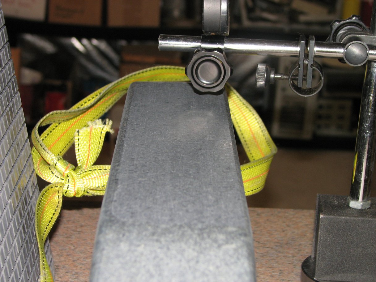
Beginning with 300 mesh diamond powder and my small lap, I lapped the top of the straight edge until it was flat and parallel to a couple thousandths of an inch.  I used a single edged razor blade to remove most of the 300 mesh diamonds and  wore away the remaining diamonds by lapping some scrap. I then repeated the process with successively finer diamond powder.  When I got to 1800 mesh, I switched laps to the larger one.  I have been using this lap only with 1800 mesh powder. I have a new lap on the way that will be used for 3000 mesh only. Dry lapping with 3000 mesh produces a nice finish for a surface plate.


I've seen some "camelback" straight edges that have a flat built into the top arch of the straight edge and others that just have a couple wooden handles that appear that they could be level with the working surface, but the top surface of my Collins Microflat straight edge is not parallel to the working surface.  In fact, it is not really even that flat.

I decided to take on the project of making the two surfaces parallel.  have a couple lapping plates that I was using to resurface a damaged surface plate.  I also have a nice selection of diamond powder ranging from 300 mesh to 50,000 mesh.  I also have a new grade A lapping plate in route to me for the finishing passes.

I started by leveling out my best surface plate (Starrett 18X24 Grade A).  I then cleaned it until spotless and placed the equally well cleaned straight edge on it.  I rechecked the level and then measured the height of the top flat from the surface plate.  I made up some maps of the top surface with the measurements I taken so I knew where the high and low points were.  Aside from not being very flat, the top surface of the straight edge really wasn't that far out of being parallel.  The lowest area (aside from the curved edge) was on the side with the Microflat sticker and it was about 7 thousandths lower than the side without the sticker.  There was a dip about an inch from the sticker side that was a couple thousandth slower than the edge, so that gave me almost 10 thousandths total that needed to be removed to make the top flat parallel with the bottom.

I started with my small 6" X 9" lapping plate and 300 mesh diamond powder.  It didn't take long to get to 5 thousandths between highest and lowest.  Another few hours and I had worked through 500 mesh and up to 800 mesh diamonds while keeping track of my progress on my map of the surface.  Now I was only a couple thousandths between the high and low areas.  Each cycle I would sprinkle the diamond powder on the granite and rub the lapping plate over the surface.  When the granite dust would become thick enough that it made sliding the plate back and forth difficult, I stopped and vacuumed up all the dust. I then took another set of measurements.  Once the measurements were put on the map, I would be able to see where I needed to take off the most on the next cycle of lapping.  Since I was using the smaller 6" X 9" lapping plate, it allowed me to concentrate my lapping on just the high areas.

Straight Edge
more to do
End View looking better
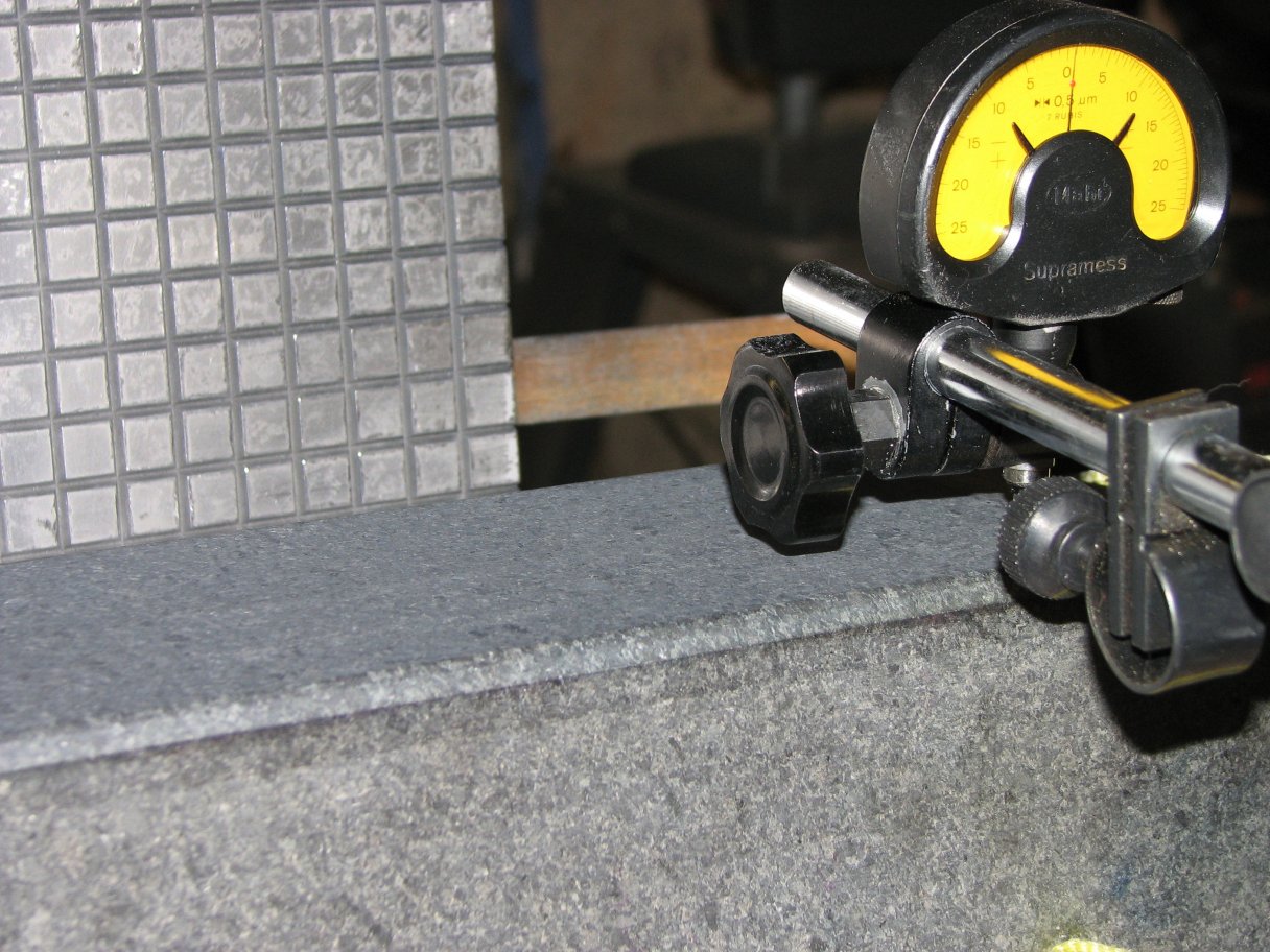
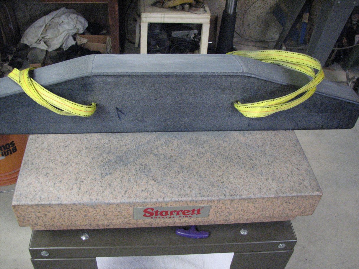
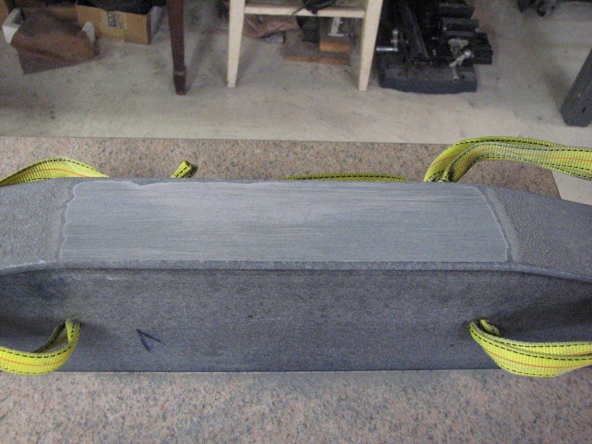
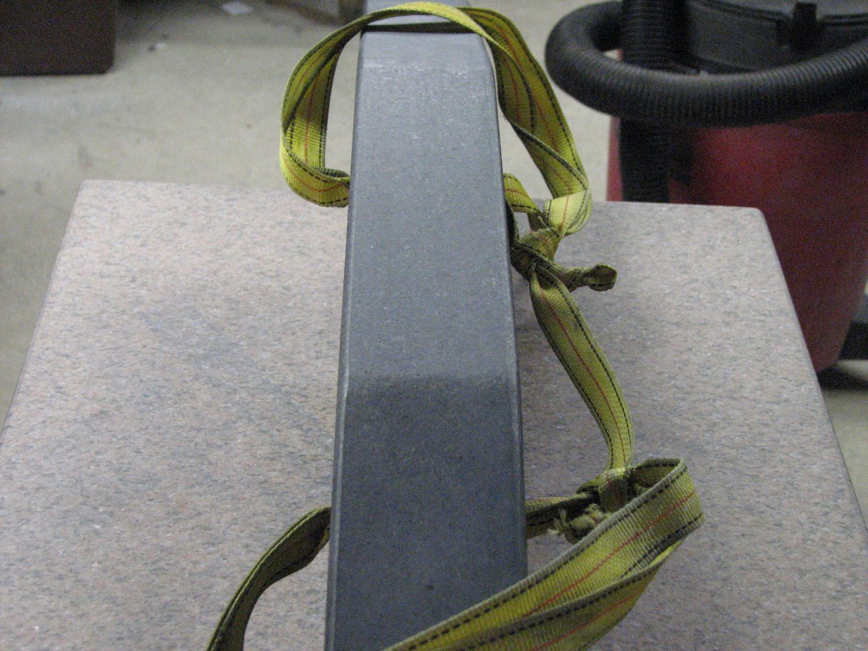
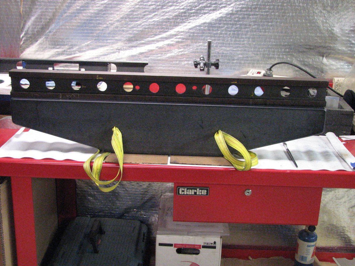
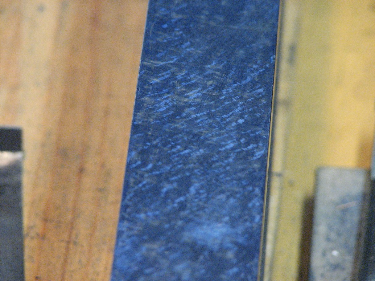
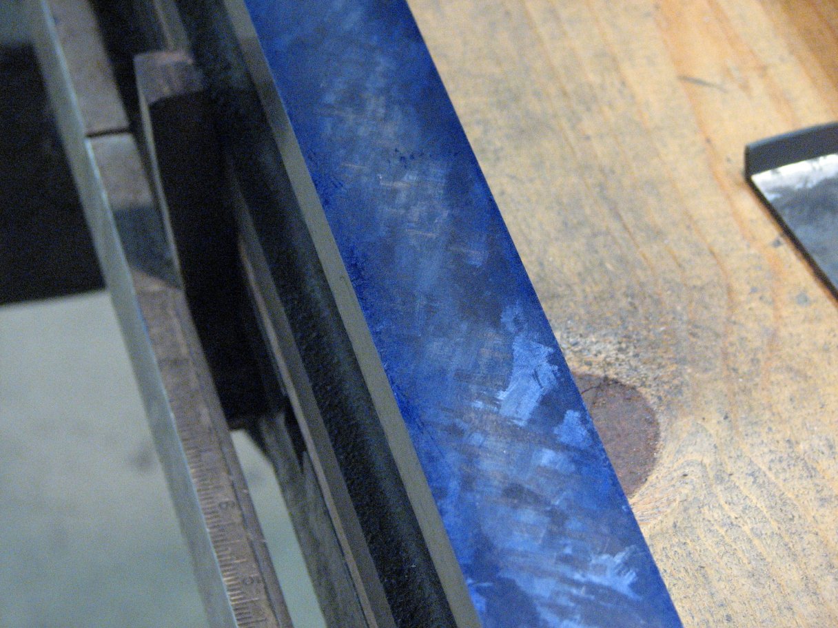
The top two shots were taken while I was still using the small lapping plate and coarse diamond powder.  The bottom two were taken after switching to 1800 mesh diamonds.  The left shot shows how the finish looks with the granite dust brushed off and the surface cleaned with surface plate cleaner.  The right lower shot shows the surface as it looks before being cleaned.  As you can see, the lapped area doesn't extend quite as far on the left side as it does on the right..

By the second evening's work,the top surface was beginning to take shape.  The curved edge on the side with the logo is a bit lower than the curved edge of the other side, so the flat area I'm creating doesn't extend quite as far on that side.  To make the flat span all of the way across the width evenly, I would have to remove much more stock than I am willing to remove.  I will live with a flat that looks a bit off-center, though however off-center it may look, it is flat and parallel to the working surface.  After I finished lapping with the small lap and 1200 mesh, I began using the large lap with 1800 mesh diamond powder.  After a few cycles of lapping with the large plate, the surface was now flat and smooth enough to be measured with my Supramess instead of my Brown and Sharpe "tenths" gage (it actually has increments every half-tenth, or 0.00005").  At the last measurement, overall flatness was now only showing 3 divisions difference between the highest and lowest spots.  Each division on the Supramess is 0.5 microns. This works out to about 0.00001969", but I generally approximate to 0.00002" per half micron.  The measurement was taken after lapping, so the measurement was probably affected by the heat of lapping and handling the straight edge.  I will re-measure tonight after letting the temperature equalize all day,then try another cycle to get it closer. (NOTE: rechecked cold, still about 1½ microns, ~0.00006")  I am pleased with the progress so far.  It didn't take very long to get it to this stage.  I have also turned the straight edge upside-down with the section I am lapping placed against the surface plate and measured the height of the 36" face.  This should amplify any slope on the flat I am creating by allowing me to measure further from the center of the flat  The length of the face that I can measure is limited by my 24" surface plate, but for that 24 inches, the difference in height from one end to the other is less than one ten-thousandth of an inch.  Since I'm not in a temperature controlled environment and didn't allow the straight edge to come to its temperature equilibrium, I'm sure that my measurements are not "spot on," but they're pretty close.  We'll see how it measures tonight. (NOTE: I rechecked when the straight edge was cold and measured 2 microns ~0.00008" difference in height from one end  to the other, or a slope of 1 micron per foot.)  At this point, I'm waiting for my new lapping plate which should help me remove the small waves in the surface that my less than perfect lapping plates have introduced. All in all, I'm very pleased with the outcome and I'm now pretty confident that not only will the straight edge come out as I had hoped, with a parallel flat for checking level, but I will be also able to get a pretty nice flat finish on the surface plate I was working on prior to getting started on the surface grinder.

Week of April 13, 2008
While I wait for UPS ground shipment
of my lapping plate to be walked slowly across the country (the Post Office beats UPS for speed in low cost shipping), I returned to scraping my 2 cast iron straight edges. Yes, it's now 2.  The one that I started on first is getting very close to being flat and smooth enough to use as a template to scrape the outboard way of the surface grinder's table.  The second one I hadn't even planned to scrape until after the grinder was finished, but I changed my mind after I got started reading Fundamentals of Dimensional Metrology by Ted Busch and cross referencing Connelly's Machine Tool Reconditioning.  I began wondering how flat my granite straight edge really was.  I had checked it every way I could think of before I started using it as a template, This included height measurements, checking it with my shop-made planekator, and checking it with my K&E 71-2022 autocollimator. All checks seemed to confirm that the face was flat and true to under half a ten-thousandth of an inch between any two adjacent areas and a tenth over the entire 36" face.  However, all of these checks require a certain amount of subjective interpretation and a measuring error of a  ten-thousandth of an inch is easily made.  I would be much more confident in the straight edge's flatness if I could perform a simple pivot test, but the test requires that I have a flat surface that is, at least, as long as the straight edge.  Since the straight edge is 36" and my longest surface plate is 24", this isn't going to happen.  However there was another way I could confirm its flatness if I scraped my other 36"cast iron straight edge.

The idea behind the check is an offshoot of the way that surface plates were created when there was no master plate to work from.  The"automatic generation of gages" is a process where three same sized plates are compared to, then scraped to or lapped to each other in a methodical order: 1 to 2, 2 to 3, and 3 to 1.  The end result of this process is that the only shape that will allow any two of the three plates to nest together, flat to flat (in any orientation) is a completely flat surface.  If we remove the "in any orientation" from the equation and orient the plates in one direction only, three helix shapes will also nest together.  To state this rule another way, two items that equal a third should equal each other.  In my situation, if I scrape one 3 foot cast iron straight edge using the 3 foot granite straight edge as the template, then do the same with the other cast iron straightedge, I should be able to put the two cast iron straight edges together and have them fit perfectly.  This will prove that the granite plate is flat.  Another benefit is that I will be able to perform the pivot test on all of the combinations of straight edges.  If you get the impression that I like the pivot test, you're right. I think it is the quickest accurate method for comparing flat surfaces. 

As for two flats that equal a third must equal each other, an example where the outcome isn't flat may convince a skeptic. Let's say that the granite straight edge is slightly concave.  One ten-thousandth low in the center of the 36"span.  I scrape each of the two cast iron straight edges against the granite one.  Each cast iron straight edge fits the granite one perfectly, but
since the template was concave by a tenth, each cast iron will be convex by a tenth of an inch. Now when I try to fit the two cast iron straight edges against each other,  just the centers will touch and both ends will be separated by two tenths of an inch.  A pivot test of the cast iron to cast iron straight edges would have the straight edges pivoting about the center.

Cas Iron on Granite
Two cast iron
2 cast iron
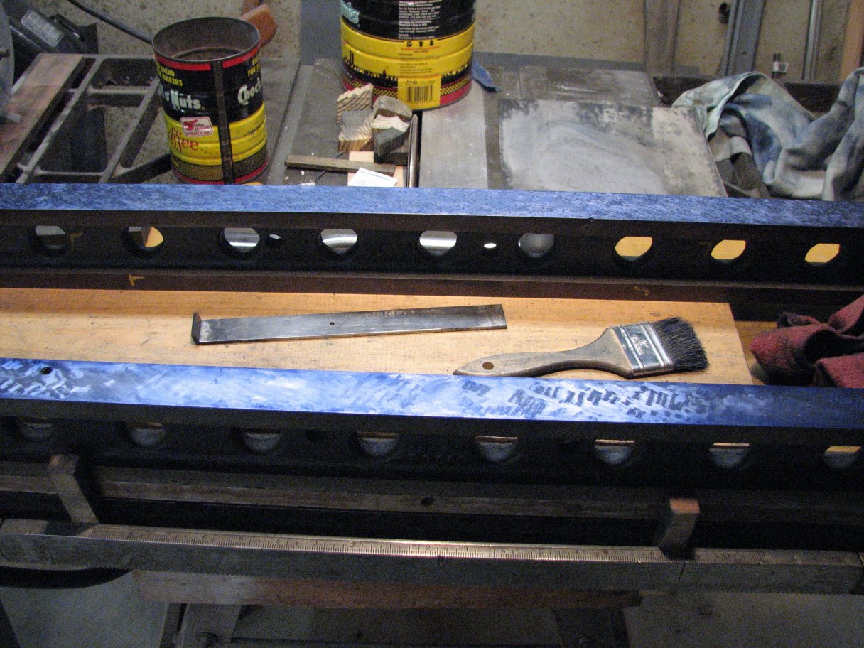
Left: Cast iron straight edge on the granite template.  Center: Two cast iron straight edges - one pull, one push scraped.  Right: Checking the two cast iron.

So much for the theory. I'm back scraping both cast iron straight edges.  After another few hours, the first one is almost finished - that is if a template can ever be finished.  As it sits now, there are high spots across the whole face and no two high spots are over a quarter inch from the closest high spot.  In the majority of areas, the high spots are closer than that.  The difference in height of the high spots to the low areas is less than a ten-thousandth inch.  I would prefer less difference in height, like less than one hundred thousandth and will achieve this given some more time, but it's not absolutely necessary to have that kind of finish for the initial spotting the ways on the grinder.

The second cast iron straight edge is just like the first in that there is one side that has been ground flat and the other was scraped flat.  The scraped side of this one is in a bit worse condition than the first.  Actually, the ground side is also not as nice as the other straight edge either.  There are some deep scratches and some dings that I have stoned so that the ridges of the ding do not extend past the surrounding surface.  Of the two sides of this straight edge, the ground side is in better shape and for sake of time,I decided to work on this side.  For now, I am just going to use this straight edge to check the master (granite straight edge), so all I need is that it is flat.  I don't need to scrape to 20 or 30 spots per inch.  I will be able to try the pivot test with far fewer spots per inch.

I decided to attack this straight edge with my pull scraper.  One of the ends of the ground surface is a couple thousandths lower than the rest of the surface and I can remove more metal, more quickly by pulling than I can by pushing a normal scraper.  My pull scrapers just a one inch wide by 1/8" thick bar of mild steel with a 3/8"X1/8"X1" carbide tip silver soldered on to the end at an angle.  With it I can remove metal like a mad man.  Using the pull scraper also produces a very nice pattern when I alternate directions by 90°.  However one down side to a pull scraper is that the high spots come out quite large - between an eighth to a quarter inch square.  Reading Connelly's book, one learns that it is preferable to have very small high spots as your surface bearing,but in this situation I'm not going to spend the extra time unless I find that the larger high spots won't give the resolution I need.

To get the first straight edge to the state it is in now, took me a couple weeks of scraping a few hours a day.  With the pull scraper, I was able to remove a couple thousandths of metal and get the surface flat but not quite totally even bearing in about 6 hours (2 days of scraping part time).  This is about one quarter of the time to do it with a push scraper.  As I stated, I still need to even out the distribution of the high spots so that I have even spacing between them over the entire surface, but I'm quite happy with how quickly I'm progressing.

I don't know if it is my technique or if it's "the nature of the beast," but push scraping tends to dig a shallow rut when I scrape the top off a high spot.  Conversely, pulling the scraper across a high spot leaves a small bump.  Multiple pulls across the same high spot leaves it flat with the surrounding surface.  I may try to finish this one side of the straight edge entirely with pull strokes to see what quality of bearing I can achieve with this method.  I know I can produce a great finish with push scraping, but if I can get a similar finish with a pull scraper, I could get more surfaces done in less time.
Push scraper 1
Push scraper 2
Pull scraper 1
Pull scraper 2
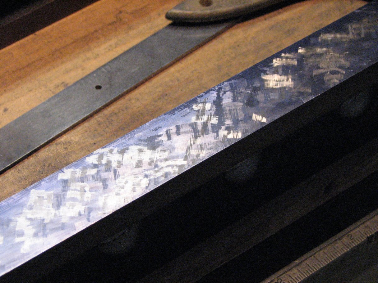
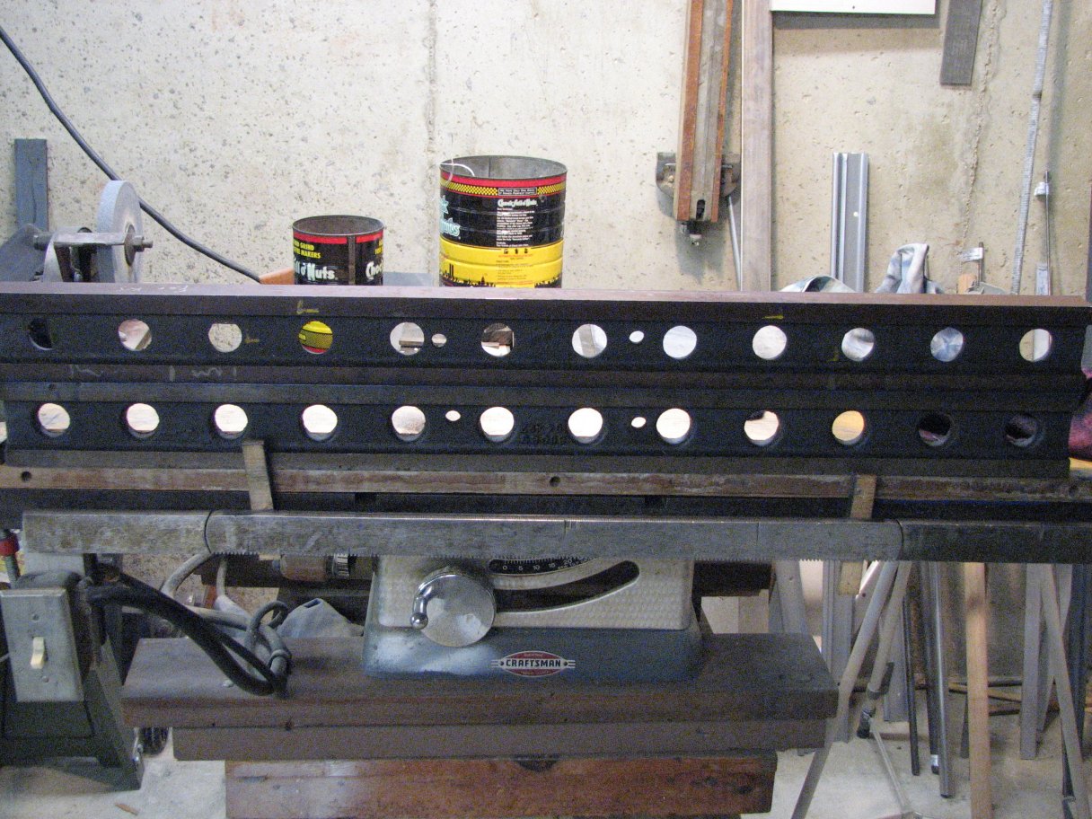
Top Row: The pattern produced by conventional "push" scraping - small high spots.
Top Left:  Both types of scrapers I use.
Top Right: Close-up of surface - silver specs are the high spots.
Bottom Left: Pull scraping surface pattern.
Bottom Right: Another view of the pull scraping pattern.  I still have a way to go to finish this surface.

I have been checking the two cast iron straight edges against each other as I continue to work on scraping the second cast iron one.  So far,the two cast iron fit together in either orientation as well as they fit with the granite template.  It appears that I have finally proved to myself that my granite template is as flat as it needs to be.  The other good news is that I soon will have a couple straightedges that may be used when the granite one doesn't fit due to height or width.

Enough writing, time to get back to scraping.


Grinder 1
Grinder 2 Grinder 3 Grinder 4 Grinder 5 Grinder 6 Grinder 7