
|

Sheldon 12"
Shaper - pg. 6
October 14, 2015 - November 9, 2015
When I finished
the last installment, I had taken a test cut. The test cut was
pretty successful considering that I hadn't used a very good
method of holding the cast iron test block to the table. I had
seemingly solved the problem with the tool head creeping downward
during cuts. The tool head lock was also working as it should.
However, I had run into another issue. Two steps forward and one
step back. The stroke made by the ram, which can be set from 0" to
13.5" was increasing in size as the shaper ran. I had set the
stroke to 7" and by the time the table moved 4" laterally to
finish the cut across the width of my test block, the ram stroke
had increased to 10". Obviously, something wasn't right.
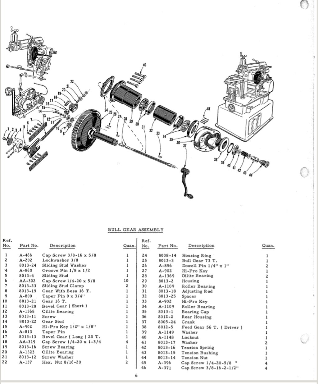
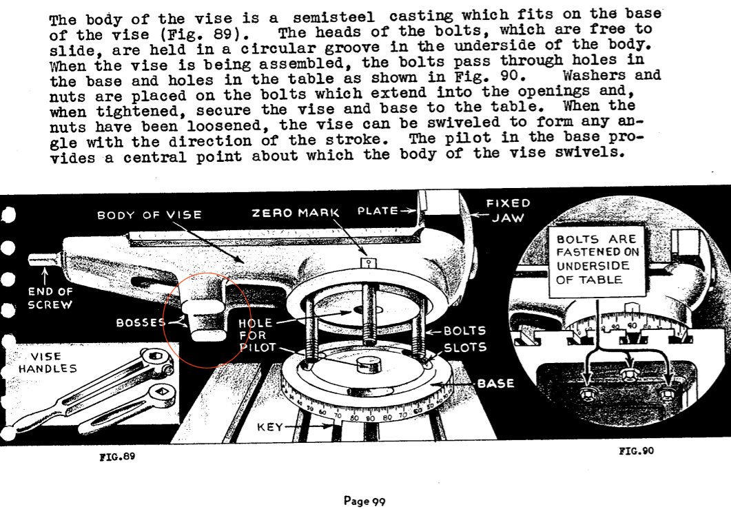
Looking at the stroke adjusting rod in the parts breakdown (below
left), I noted that part #44 was labeled as a tension nut (expand
the image for the names of the parts). Since it had a spring
behind it, I was hoping that this nut would be able to make the
adjusting shaft a bit harder to turn and solve my problem. To get
at this nut, I pulled off the two arms (#5 and #33 in the second
picture). I also removed the two screws that appeared to hold the
cover in place. At that point, I didn't realize that the parts
image I was looking at (below left) didn't have all of the parts
shown. The screws are part #21 on the second image. With
everything I could see that appeared to hold the cover in place,
it wouldn't budge. I messed with the cover for about an hour and
called it quits for the night.
The next day, I looked through the parts drawings again and found
the second image. This time I saw there were also two taper pins
(#20). One next to each of the two screws. I measured both ends of
the one taper pin I could easily get to and found that the small
end was on the back side of the housing. There was no way I could
get a pin drift and hammer in that small space to knock out the
pins. What to do? I cobbled together a C clamp with a pin on one
end and a socket on the other to try and press the pin out, but
knew that the effort would be futile. It was. These pins were
stuck in place.
 |
 |
| Page 6
from the Sheldon Shaper parts manual. Click to enlarge and show the part names. |
Page 8
from the manual. Click to enlarge and show the part names. |
I had noticed
that there were two studs with locking nuts on the top of the
cylindrical housing that attached to the rear housing of the cover
I needed to remove. These are not shown on either of the parts
drawings. When I was cleaning the shaper and trying to understand
the purpose every nut and bolt, I had assumed that these were for
some sort of adjustment, but what that adjustment could be I
didn't know. Each of the studs had a socket for a 1/4" Allen key
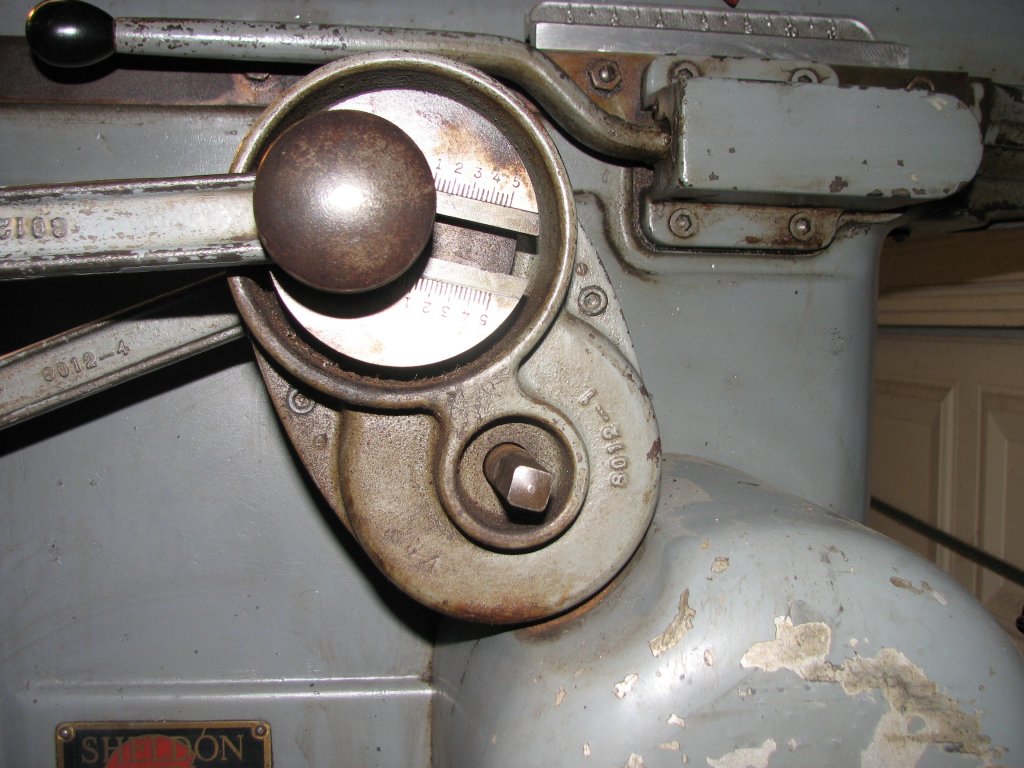
and the lock bolts took a 3/4" wrench. You can see one of the
studs with its lock nut on the 6th image on top of the
housing on the right. With nothing left to try, I decided to mark
the position of each of the studs so I could return them to their
current position and see what happened if I loosened them up. This
attempt solved the problem of removing the cover. With both studs
backed off by 1/2 turn, the whole housing assembly was free to be
pulled off of the machine. The two studs press on the inner
cylindrical housing that attaches to the shaper body and hold this
housing in place. To replace it, it appears that you just push it
back on and position it so that the two arms fit and tighten the
studs and lock nuts.
 |
 |
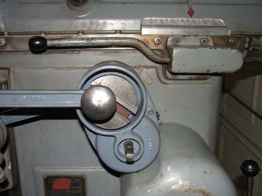
| The
stroke adjuster rod is the lower squared shaft. The upper domed knob lets you adjust the amount that the table advances per stroke. |
Once
the whole assembly is removed, you are looking at the
stroke adjustment nut and the gear that drives the table
advancement. |
Once the housing
assembly is removed, I found that I didn't need to remove the
cover that I had been fighting to get off unless I wanted to take
a look at the gear that drives the table indexing for its side to
side travel. This is another case where experimenting can lead you
to a discovery. Even though it wasn't necessary for the current
repair, I decided to go ahead and drive the old taper pins out and
remove the front cover. As long as I had the assembly out, I might
as well clean the rust off of it and check the gears for wear.
After all, this is a 60+ year old machine and I am assuming that
this is the first time it has been disassembled this far. The
taper pins came out with a couple whacks with a hammer on a pin
drift. The pins were a little rusty and the small ends had been
mushroomed a bit by my knocking them out. Contrary to my usual
situation of not having the correct pins in stock, I happened to
have a good supply of the correct taper pin - #2 pin, 1" length. I
have more of these than I could ever use. If you need a couple,
send me an email and I'll drop a couple in the mail for you.
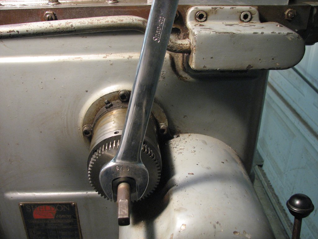
With the
adjuster nut exposed, it was time to see if I could increase the
tension on the adjusting shaft so that the shaft wouldn't turn on
its own. The adjuster nut takes a 1 1/8" wrench and I had assumed
that I would need to tighten the nut a small amount to add some
tension to the shaft, but I was wrong. To be on the safe side, I
again marked the position of the nut on the shaft so I could
return it to the position I found it in and then tried tightening
the nut clockwise by a quarter turn. Tightening the nut took
tension off the shaft. OK, no problem, let's try turning the nut
counter-clockwise. I turned the nut back a quarter turn, then an
additional quarter turn. The shaft appeared to get a little harder
to turn. I went another quarter turn and the shaft was now locked
up from rotating. I backed off (turned clockwise) about a 1/16th
turn and tried cranking the adjuster rod again. It seemed to have
more tension but wasn't too hard to turn. I will try it here. If
the truth be known, I have no clue whether my adjustment will
solve the problem. However, it seems like it should. I guess I
will know soon enough.
Since there is a
fair amount of dirt and rust on all of the parts in this assembly,
I decided to clean things up a bit before I reassembled and tried
another test cut. While I would like to reassemble the machine and
take a test cut right now, I know myself too well. If I don't take
the time to clean up the rust, it will not get done until I decide
to strip the whole machine for painting. Since that's not on my
agenda right now, I might as well do what I can to get rid of the
rust.
 |
 |
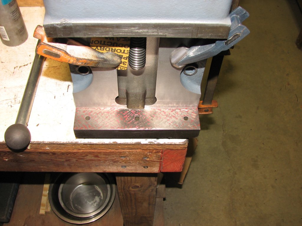
| A 1
1/8' wrench fits on the tension nut. It appears that
turning the nut counter-clockwise makes the adjustment
shaft harder to turn. |
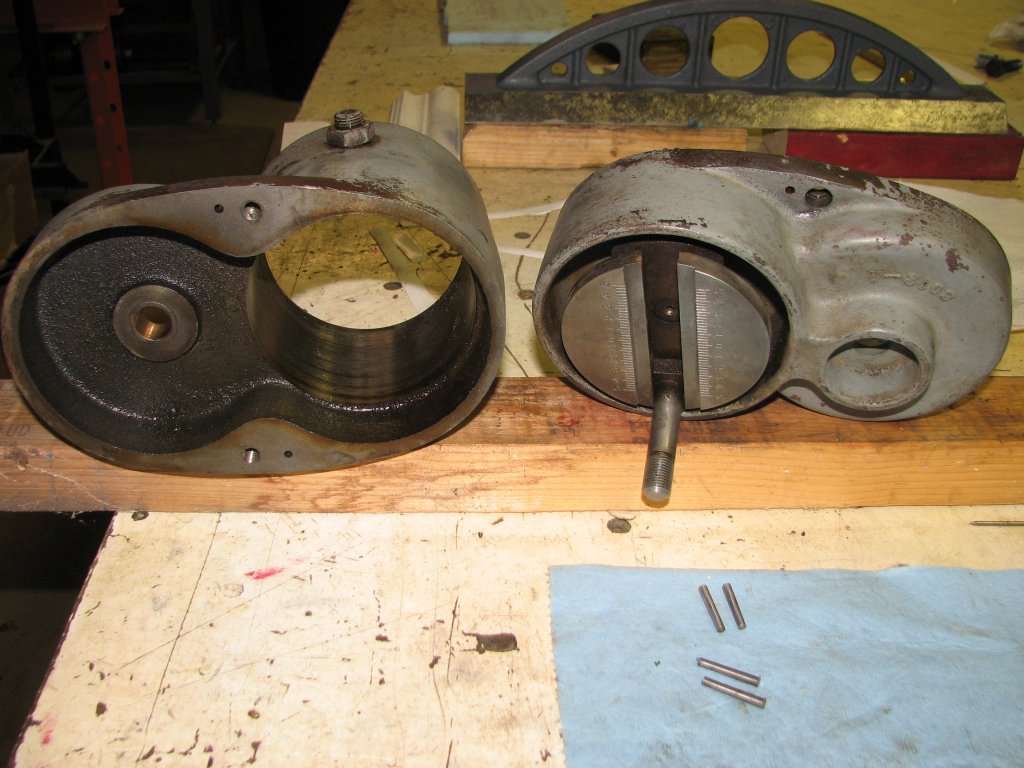
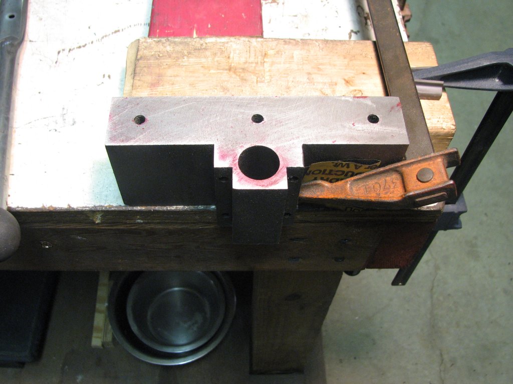
The
parts of the housing and cover that I was having trouble
separating. I have some new #2 taper pins along with the
old ones. |
It turned out to
be well worth my time to strip down the housings to clean the
parts and give the painted parts a better coat of paint. I ended
up finding a couple parts that might have been lost if I wasn't
paying close attention. The two studs with lock nuts that secure
the housing assembly to the cylinder on the side of the shaper do
not bear directly on the cylinder shown above right. There are two
wafer thin bronze shoes that sit at the end of each stud that fit
between the studs and the cylinder they bear on. One fell out
while I was cleaning up the rear cover housing. As soon as I saw
it, I knew what it was and scolded myself for not checking the
bore of the housing more carefully. I was lucky it didn't end up
on the floor to be vacuumed up later in the day. The other disk
shaped shoe was still on the end of the second stud. I removed the
shoe and both studs and continued cleaning the housings so I could
give them a coat of paint. I got one coat of paint brushed on in
the late afternoon and another coat later that night. Hopefully I
will be able to reassemble everything tomorrow and test to see if
I have fixed the issue with the stroke increasing on its own.
To get the
eccentric off (lower left photo - the part with the divisions),
you need to remove another taper pin. This one is driven out from
the gear. The size of this one is a #1 - 1 1/4" in length. This
pin came out easily and can be reused, but I have some of these in
stock also. I may not have all sizes of nuts and bolts on hand,
but I have an excess of taper pins. All of them received from a
guy who was down-sizing his workshop. With the taper pin out, the
gear pulls off from the rear and the eccentric pulls out from the
front with the attached shaft. I cleaned and buffed all the shiny
bits and added a coat of paste wax to help to keep them from
rusting. I wax pretty much everything that is bare metal after
finding that just wiping parts with way oil every few months
wasn't enough to stop the surface rust I get in this shop. I have
only been using the carnuba paste wax for a couple months, but it
seems to protect the bare metal very well. I put it on thick and
don't buff all of it off. A quick wipe with a rag or shop towel on
parts like squares of parallels gets them ready for use. So far, I
like this a lot better than way oil or the spray on anti-rust
coatings, but I have yet to go through the worst part of the year
for rust. Spring and early summer seem to be the rust seasons in
my shop.
Another
interesting thing I found is that the two bronze bushings that
support the eccentric's shaft have no provision to be oiled. Page 8 of the parts manual
says that they (#9 & #15) are bushings. Other bushings on the
same page are listed as Oilite bearings. From their appearance, I
believe these are the Oilite type also. Oilite bushings are made
from sintered bronze and are oil impregnated, but I would prefer
to be able to oil them when I use the shaper. Since there is no
way to oil them without disassembling the housing, I will recharge
them with oil. To recharge them, you soak them in mineral oil that
is heated to 80° to 100°F and let the bushing cool to room
temperature. I have also read that they can be recharged by
placing the bushings in oil under a vacuum. I will soak them in
heated oil and let it go at that. The shaft that turns the
eccentric spins slowly and after 60 years, there is very little
play between the bushings and shaft. The gears are also in great
condition. There is virtually no wear, just a nice even polish to
the face of the teeth.
 |
 |
| Two
bronze shoes that fit on the ends of the two locking studs
that hold the assembly to the shaper. I am starting to
clean things up a bit. |
The
assembly is back together and I am ready to test it. This
didn't go so well, but I learned a few things that helped
me make it right. |
After heating up
some ISO Grade 32 turbine oil and soaking the bushings in it for a
couple hours, I cleaned up the mess and reassembled the housing. I
used some grease to hold the bronze shoes in place and reinstalled
the housing. The whole process went pretty quickly and I was soon
ready to reattach the two arms. The rear arm secures the housing
to the back of the table advance mechanism which is connected to
the cross rail. The front arm connects the eccentric to the front
of the advance mechanism and is responsible for moving the
ratcheting cogs that move the table either left or right.
When I had
initially checked the tightness of the studs on the housing, I had
found that the two studs were not all the way tightened down. Once
I found that loosening them allowed me to remove the housing, I
didn't give their tightness much more thought. When I reinstalled
the housing, I cranked the studs until they fully seated the shoes
against the cylinder they pressed against. I reinstalled the two
arms and figured that I was ready to take a test cut. I mounted
the test block on the table and started to raise the table into
position. After one or two cranks, the table wouldn't elevate any
more. After a couple moments thought, I realized that the rear arm
(below right) tied the housing to the cross rail. The cross rail
is what moves when you raise and lower the table. Instantly, the
signs of wear on both the shoes made sense. The housing was
supposed to rotate as the cross rail was raised and lowered. If
the housing couldn't rotate, it bound up the cross rail. It was
one of those "Duh" moments.
I backed off
both the studs by enough that the housing could rotate and I could
now raise and lower the table. I was set. Or so I thought. I
started my test cut and by half way through the 4" wide cut, the
stroke was advancing on its own again. I removed the arms and
pulled off the housing once again. I checked the tension on the
stroke adjusting shaft and it turned a little easier than I
thought that I had set the tension to. I would try again. This
time, I turned the adjusting screw counter-clockwise until the
stroke adjusting shaft had a good deal more tension while turning
with the crank. If I get it right this time, I will put a constant
reading torque wrench in place of the crank to check the amount of
resistance when I turn the shaft. Hopefully having a reading in
inch or foot pounds will help in case I need to go through this
again.
 |
 |
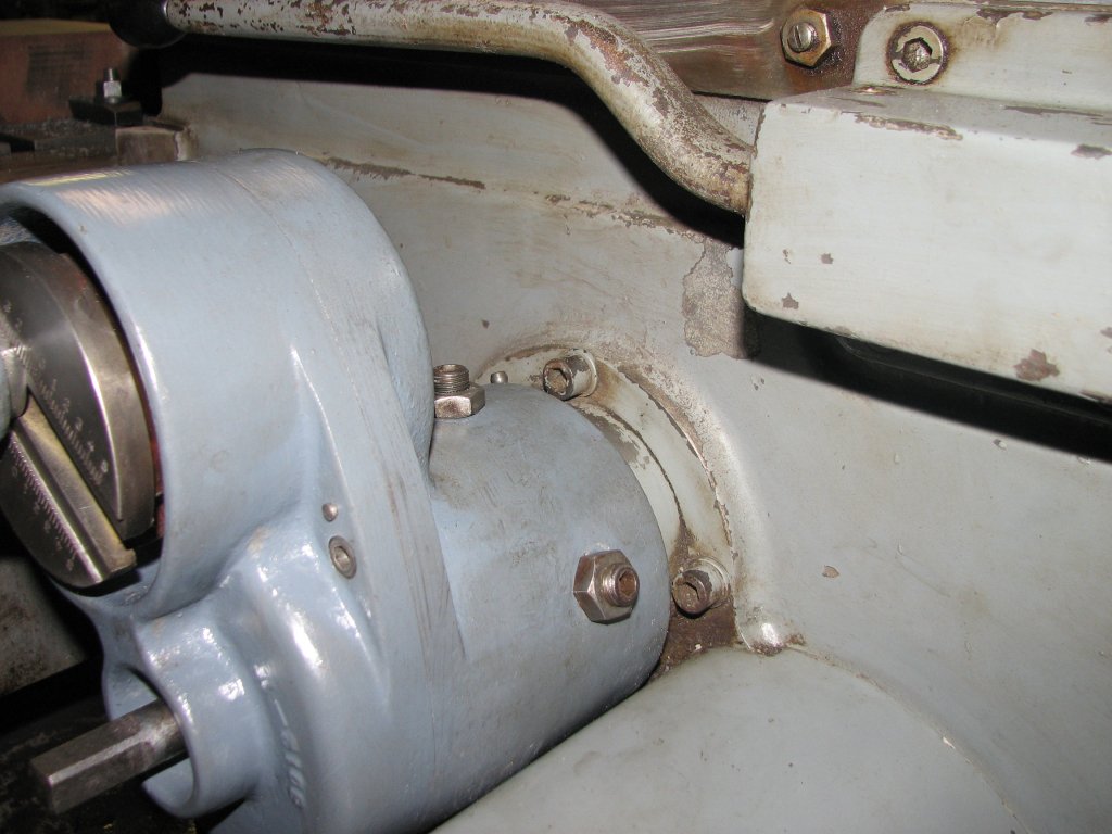
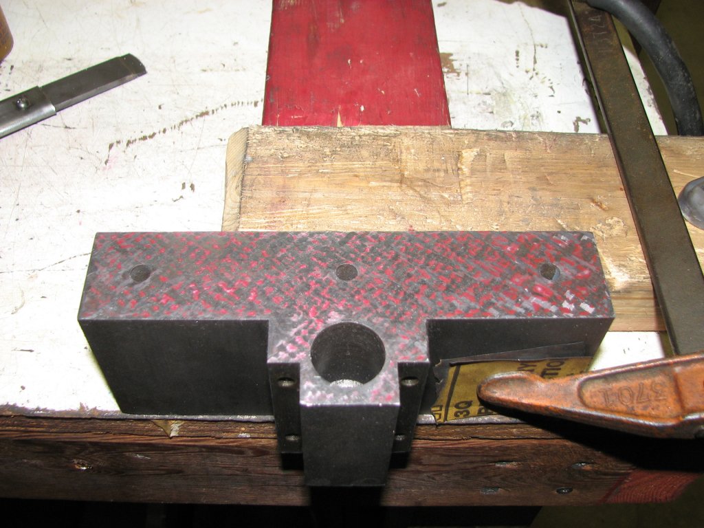
| The two
studs with lock nuts on the rear cylinder are not meant to
hold the housing stationary. The housing needs to be able
to rotate. |
The
rear arm is attached between the shaft on the table
advance and the housing. If the housing doesn't rotate,
the table height won't adjust. |
I reassembled
all of the pieces I had removed and tried cutting my test block. I
had a better outcome this time. I was able to cut the whole 4"
wide surface without the stroke straying from where I had set it.
At this point it is a little early to say that I have fixed the
issue. I will try some more cuts tomorrow. If it holds the
adjustment without the stroke increasing, I will then be a bit
more confident in saying that it appears to be fixed.
The next
evening, I spent a few hours running the shaper. The issue with
the stroke increasing by itself appears to be fixed.
 |
 |
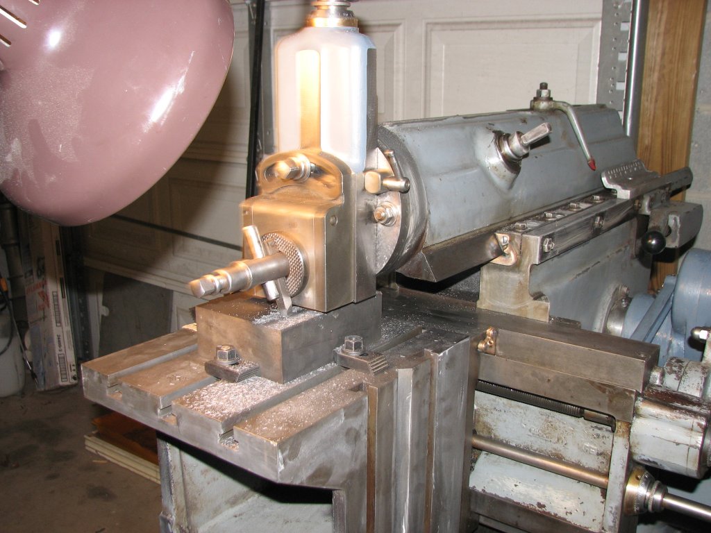
| The
first test cut. I am using some milling hold-downs and
wedges to hold the block in place. The results were only
fair. |
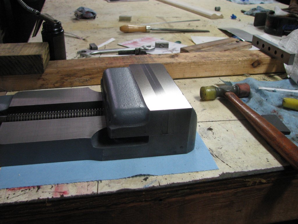
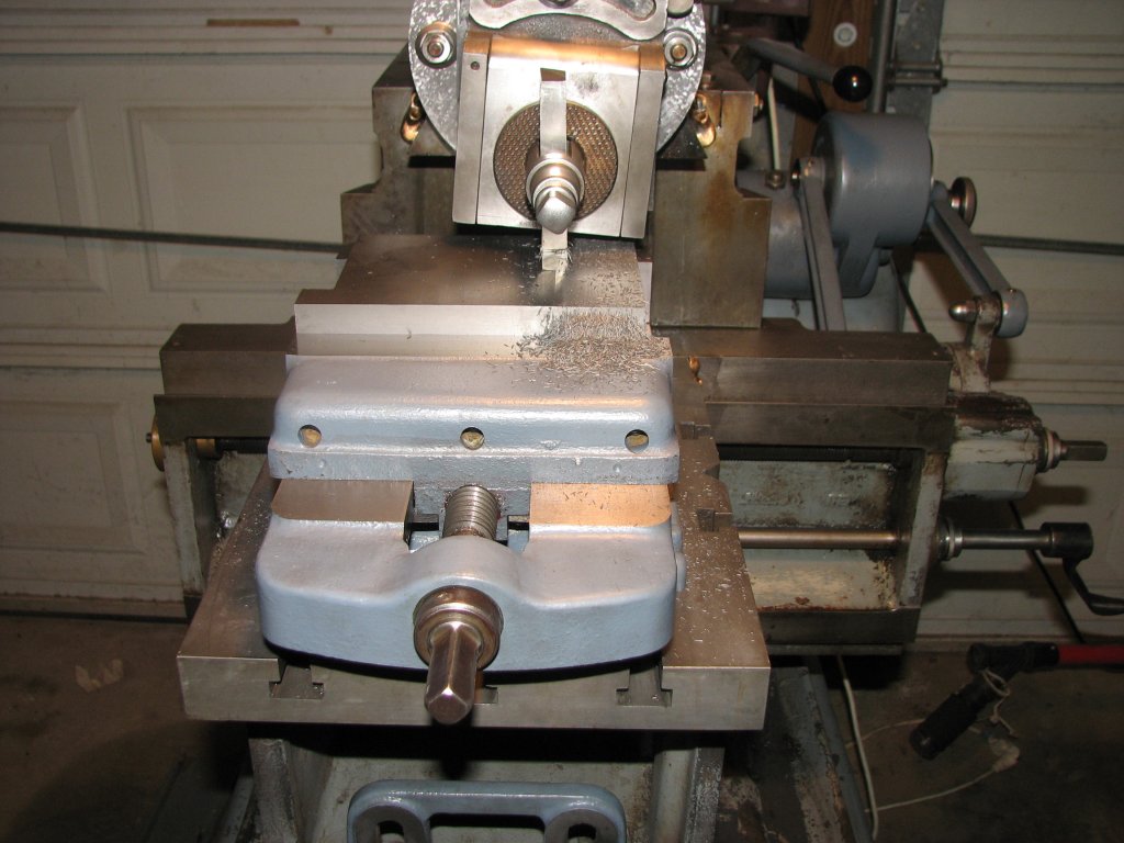
Planing
the rails of the vise body. This is a much more secure
setup and the accuracy of the cut reflects this. |
I planed a few
pieces of different sizes and materials, all of which were mounted
directly to the table with studs and wedges. I had given up on
using the two piece vise and was now using blocks and wedges.
These have their own problems, but I will get to that in a
moment. Each piece, after being planed on two opposing
sides, was then transferred to the surface plate and checked for
being parallel with the plate. My worst case readings were about
0.001" per 6" out of parallel in the X axis. The Y axis
measurements were always about half the error of the X axis.
Not bad, and certainly better than before I started scraping, but
not as good as I thought it should have been. I have read that
being able to plane to around a thousandth is thought to be pretty
good for this size of machine. Remarks like "the shaper isn't a
surface grinder" come to mind, but I am sure that with some time
to refine my setups, my planing errors will come down a little.
 |
 |
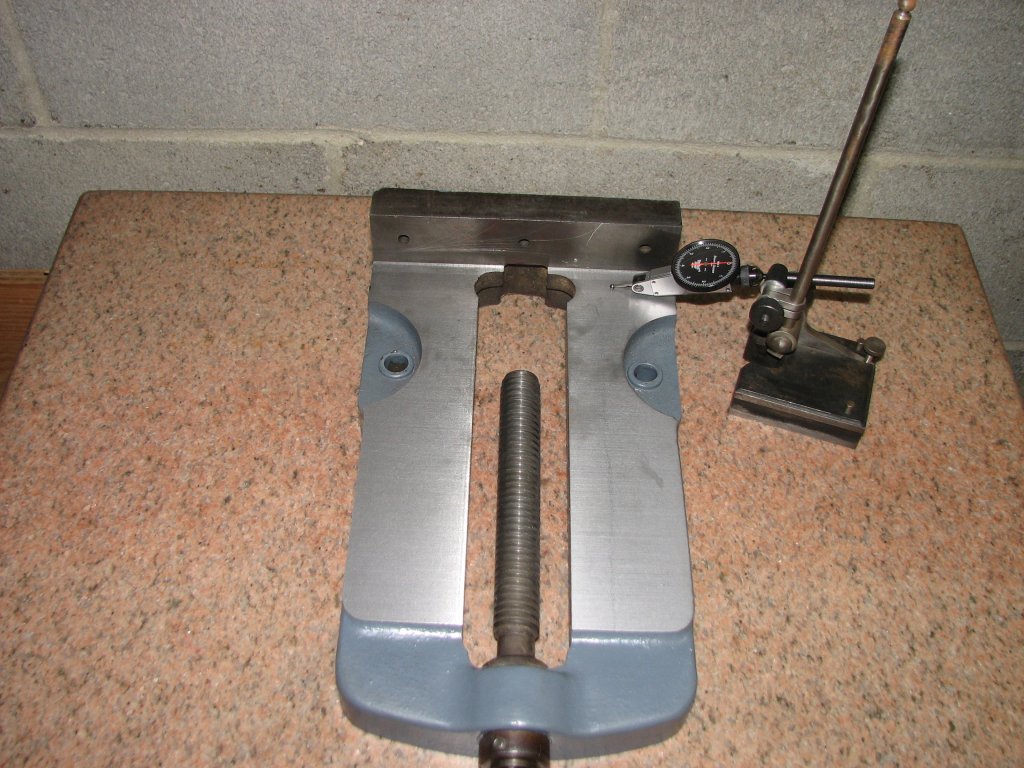
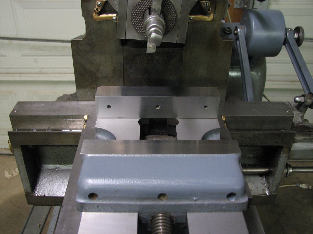
| Checking
for parallel between the vise rails and the bottom scraped
surface. |
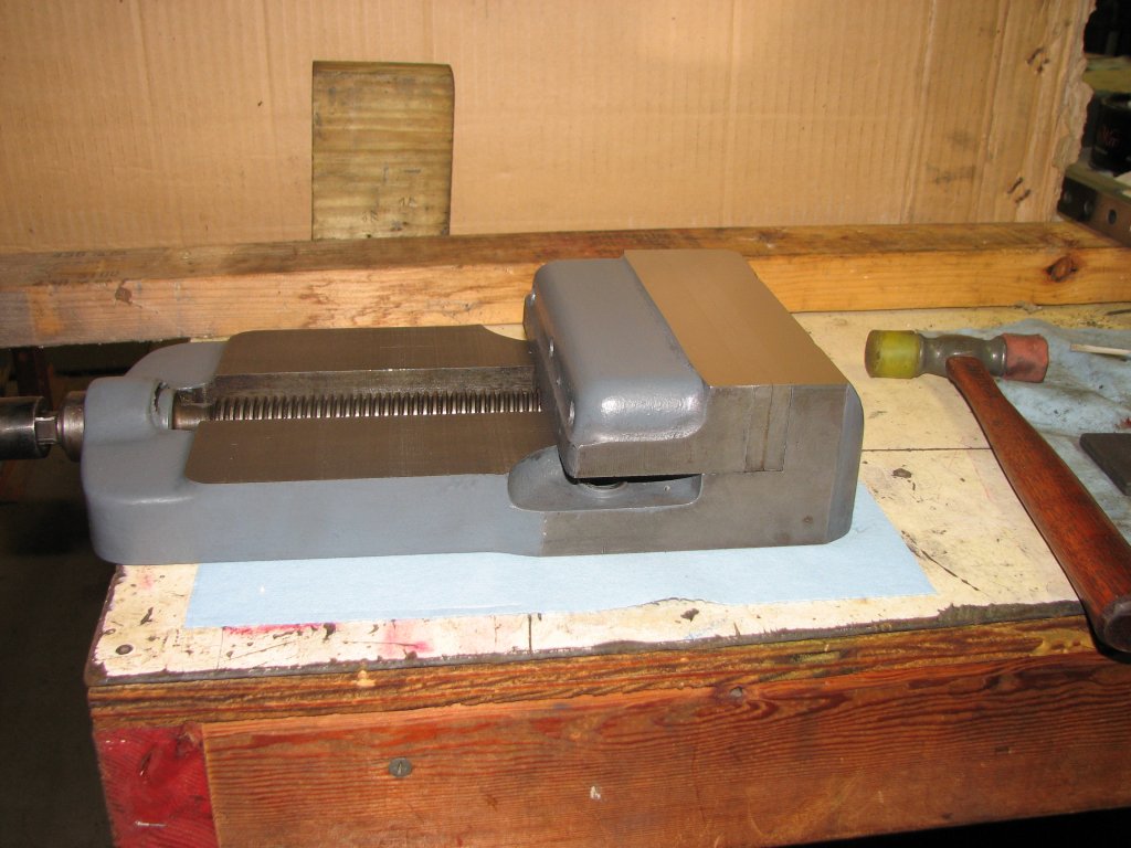
The
surfaces came out pretty close to dead on. I am very
pleased with the results. |
Since the stroke
was now staying put, it was time to plane the rails of the shaper
vise body. With the bolt holes in the vise body to allow me to
hold it to the table securely, I thought that this would be the
first good test of how accurate the shaper was. The bottom of the
vise body was scraped flat and I had rechecked the table with a
straight edge to make sure that there were no burrs. Due to the
vise jaw and the need to under cut the bottom of the vise jaw a
small amount, I decided to use a tool bit mounted directly to the
clapper. Not the best setup due to a lot of extension on the tool
bit, but it ended up working very well. The vise rails came out
almost dead flat and parallel with the bottom of the body. The
finish came out nice enough that I don't feel the need to scrape
it. I think that my test blocks were coming out a little less true
than the vise body did due to the poor method of holding the test
blocks to the table. With the test block only being held by the
side forces from wedging against some hold down clamps, I wasn't
getting as much downward force as with the vise body. Even though
I had tapped the block with a mallet to seat it, it's hard to come
close to the force exerted by bolting something to the table.
 |
 |
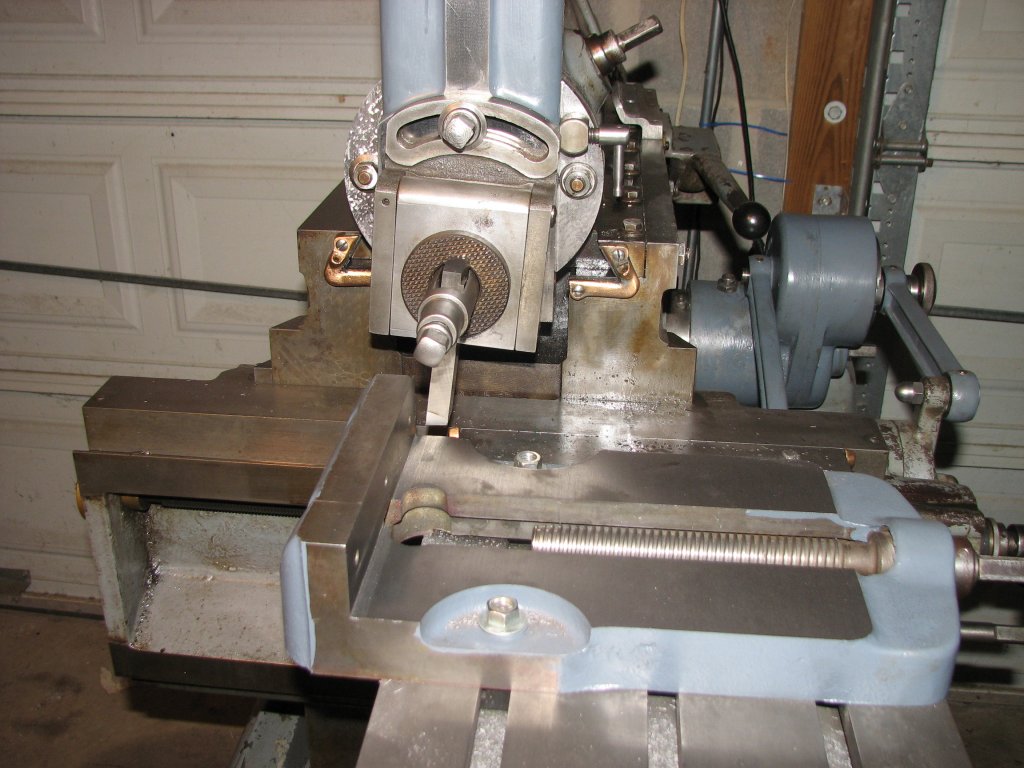
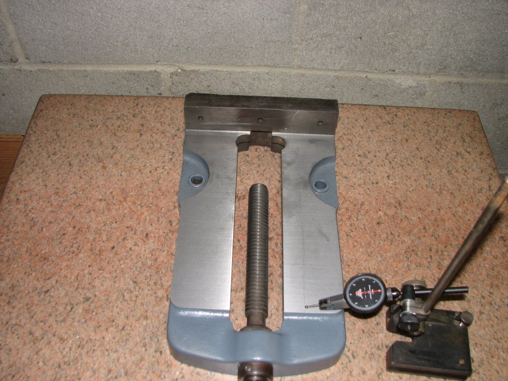
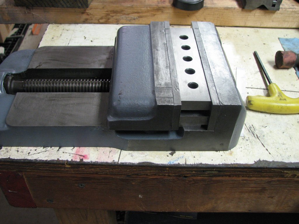
| The
vise has been mounted to the swivel base and I am now
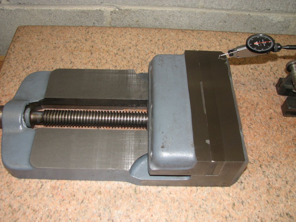
checking parallel for the whole assembly. |
Again,
the results are very good. The time spend scraping the
vise surfaces has paid off. |
I mounted the vise body on the swivel base and measured again on the surface plate. It appears that I did a pretty good job on my scraping. The rails are withing a couple tenths of being parallel everywhere I put the DTI. I am happy with the outcome. The next step was to test and grind the vise jaws or make some new ones. I will probably end up doing both. The vise jaw faces were pretty scarred up and were both a little bowed. The worst one allowed me to slip a 0.010" feeler gauge under the center. I took the jaw pieces to the hydraulic press and set up a couple blocks to try and get the bow pressed flat. This is tricky work, but after an hour or so, I had both jaws flat enough to put them on the magnetic chuck of the grinder. I ground 0.007" off of one side of both jaws, then flipped them over and ground another 0.008" off the other side. I printed them on the marking surface plate and they looked good.
 |
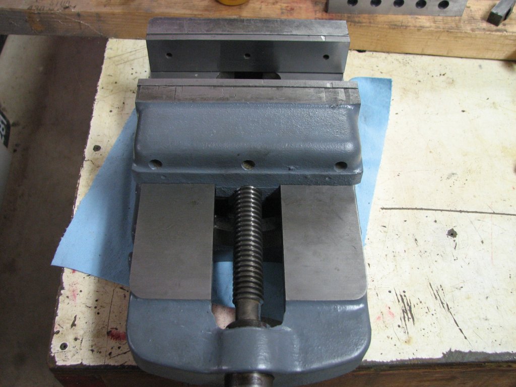 |
| The jaw
faces are not in the best of shape. That's a 0.010" feeler
under the jaw on the right. |
The jaw
faces are attached for a test fit. Some testing revealed
that I still have some work to do. |
I mounted the
jaw faces on the chuck. I then stacked two, half inch thick, one
inch wide, by six inches long parallels on the rails and tightened
the vise jaws snug. The bottom parallel held tight, but the top
one could be moved. There wasn't a lot of slop, but there was
enough that the top parallel wasn't trapped by the jaws. Hmm, this
isn't good. The jaw faces don't seem to be parallel.
I had already
measured and machined a step into the two rub plates on the
underside of the rails that hold the moveable jaw tight against
the vise rails. I did this to adjust for having planed the rails.
Planing the vise rails had introduced more of a gap between the
rub plates and bottom of the vise rails. I had relieved the
portion of the rub strip that mounted to the moveable jaw so that
I had less than a thousandth clearance between the rub strips and
the bottom of the rails. The moveable jaw was as tight to the
rails as I could get it without making the jaw hard to move. It
was now time to do some measuring to see where the problem lies. I
had hoped that the jaws would have been perpendicular with the
rails, but knew that this probably wouldn't be the case. While
I've rebuilt a Kurt clone import mill vise with good success, this
vise wasn't quite the same. Not to shift the topic, but Kurt has
some good instructions for rebuilding their D series vises here.
The mill vises like the Kurt D series have a removable fixed jaw
aligned with a key. The Sheldon vise has the fixed jaw cast along
with the base. From what I have read, for the best holding
ability, the fixed jaw should tilt a bit inward rather than being
machined or ground at exactly 90° to the rails. This is done so
that when the vise is tightened, the fixed jaw flexes into a state
of being very close to 90° rather than obtuse and past 90° by some
small increment.
 |
 |
| Scraping
the fixed jaw so that the top of the jaw is angled toward
the rear jaw by a couple tenths. |
The
moveable jaw's first print after knocking down a few burrs
with a coarse stone. |
Since I need cut
the stationary jaw to be a bit less than perpendicular, I thought
that the following operations could do what I needed: from least
to most accurate. Plane it on the shaper, if I shimmed the vise
base on the table to the correct angle. I wouldn't want to try and
set the tool head to cut a fraction of a degree. Using a cup wheel
on the grinder would also work, again by shimming the vise to
achieve the very slight angle I needed. Last, I could scrape the
fixed jaw. This would be a little more time consuming than
grinding, but since this is not a sliding surface, the points
count doesn't need to be very high. I chose scraping. Since
scraping takes metal off more slowly, I stood a better chance of
getting the angle where I wanted it. I clamped the vise body to an
8" angle block and clamped the block to the bench. I checked my
progress with a precision square backed by a bright light. When
the jaw was flat and I could just see a hint of light at the
bottom of the fixed jaw, I stopped scraping. It took less than an
hour to complete.
I reassembled
the vise with the hard vise faces and again tested the holding
ability. It was better, but not quite there yet. Time to check the
moveable jaw. Once the jaw was on the bench. I did what I could to
knock down the high points with a rather coarse grit stone, then
cleaned it, and put it on the marking plate. Aside from a ring
around the large hole where the screw resides there were only a
couple of burrs touching the plate. A couple cycles later, I got
to see something interesting. In the picture below left, you can
see that there is a hollow area across the top center of the
moveable jaw. Since the jaw face still showed the machining marks
from a large face mill, at one point in time it was fairly flat.
Now, not so much. I am always interested in trying to figure out
how surfaces get out of alignment. If I had to wager on this one,
I would put my money on compression/deformation of the top center
of the jaw from years by having smaller objects held in the center
of the vise and then cranking the jaws very tight. When I first
checked the vise, there was a lot of slop between the moveable jaw
and the rails. This meant that the top of the jaw was tilting away
from the fixed jaw when tightened. I'd guess that some
operator kept tightening the jaws to try to overcome the fact that
the work wasn't being held securely. The top center of the
moveable jaw is dished by about a thousandth. Time to do some more
scraping.
A couple sets of
step scraping passes and some finish scraping to even out the
points count a bit and I was ready to check the holding ability of
the jaws again.
 |
 |
| The top
center of the jaw is a bit hollow. I have more rough
scraping to do. |
After
another round of step scraping and some work to get a more
even bearing, I was done. |
This is the
first time that I have tried stacking parallels to check if the
vise jaws were true with each other. I don't know if I read about
this procedure somewhere or I came up with it on my own, but it
seems to work very well as a test. Out of curiosity, I checked my
milling vises using the same method. All of them passed the test
with only a slight snugging of the screw.
I reassembled
the shaper vise and tried the test without the jaw facings. The
parallels were both held tight with only the slightest pressure
from the screw. I then cranked the screw tight and there was no
change. Both parallels were still trapped tightly by the jaws. I
placed the top parallel at the very top of the jaws and repeated
the test. Same results and still good. I reattached both ground
jaw faces and tested again. I had figured that I would get the
same results, since I had checked the jaw faces with a micrometer
and on the surface plate and found that the grinding had brought
them to within a half tenth of being parallel. However, it was
still a nice confirmation that with the faces installed, that
testing with the parallels passed with flying colors. Cool. I had
succeeded in aligning the jaws. The next step was to get the tops
of the jaws parallel with the vise base.
 |
 |
| I
tested the jaw alignment with the top and bottom parallels
separated by a quarter inch. |
After
some time on the grinder and about 50 thou. removed, the
tops are parallel within 0.0002". |
The tops of the
jaws had a fair amount of battle scars. For about 60 years of age,
they looked about like you would figure. Not horrible, but the jaw
tops showed signs that, at least a few of the operators weren't
paying attention during its life. Initially, I was going to true
the tops of the jaws with the shaper and finish with grinding, but
my surface grinder hasn't seen a lot of use in the past few years
and it could do with some exercise. I had done a rough measurement
and knew I needed to remove at least 0.035" to get the tops of the
jaws lined up and this measurement didn't include the battle
scars. I ended up grinding off 50 thousandths and still had a
couple divots left. I ground pretty aggressively and was grinding
dry, so I introduced a bit of heat in the vise and that wasn't
good for accuracy. I decided to stop for the night and do a quick
measurement of the jaw tops on the surface plate, then grind the
remainder the next day. Even with a slightly warm vise, I measured
less than 0.0002" discrepancy over the seven inches of the jaw
tops. I hope to improve on that tomorrow.
 |
 |
| Another
0.009" was removed and it looks nice. A texture difference
shows between the cast iron of the body and the steel of
the jaw faces. |
After
putting the vise on the surface plate, I found less than a
tenth height difference after loosening and snugging the
jaws. I am pleased. |
With my grinder
coolant pump waiting on a roto-flex seal and the make-shift pump
not having enough head pressure to give a decent flow, I again had
to grind dry. I ground another seven thousandths off and had
finally removed all of the divots. I didn't feel any appreciable
heat in the jaws, but let them sit for a while as I re-faced the
stone for the final passes. I took a couple five tenth passes, a
few two tenth passes and then sparked out. With coolant, it only
takes a couple passes until there are no sparks coming from the
wheel as it traverses the work. Grinding dry seemed to take quite
a few more passes. When the grinder wheel finally stopped making
sparks, I was done. I have to say that changing the belt on the
grinder made a big difference. I am now seeing none of the
patterns on the ground surface that I saw with the old belt. I was
quite pleased with the surface finish. The finish of the ground
cast iron looks a little darker than the steel jaw faces, but both
the CI and the steel look very smooth and uniform.
I moved the vise
to the surface plate and was happy to see that I had improved the
surface. I was now reading less than a tenth difference in height
on the seven inch width of the jaws. It's about a half tenth
concave in the center. I was quite pleased that I could open and
close the vise jaws and measure no lip when I passed the stylus
over the point where the jaws met. If I cranked down hard on the
handle, the rear jaw lifts a few tenths, but that is to be
expected with the design of this vise. Overall, I think I did a
pretty good job. I will be interested to see the outcome when
trying to true up my test block.
As seems to be
typical for me, on the afternoon I finished grinding the vise, the
new roto-flex seal arrived. Hopefully I will again have a working
coolant pump on the grinder soon.
 |
 |
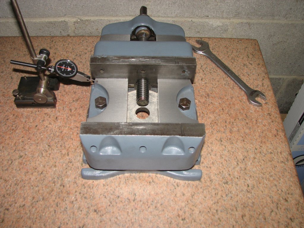
| After a
few months work, the swivel vise is finally mounted back
on the table. It is now much more accurate than when I
began. |
After a
couple of test cuts, I learned a few things and was able
to get the top surface very close to parallel with the
bottom. |
I touched up a
couple spots on the vise where I had damaged the paint and the
next evening, I mounted my cast iron test block in the vise. I
added some thin squares of paper under each corner of the block
and tightened the jaw. The end of the block nearest the moveable
jaw lifted a very small amount. Just enough that I could move one
of the papers a fraction before it became trapped again. I used a
mallet to tap down the block and snugged the jaw a little tighter.
All four papers were now trapped, but as I would find out, not
trapped well enough. I set the ram travel and position and turned
the shaper over by hand using the Reeves drive pulley. I happened
to turn the pulley the opposite direction and the ram didn't move
until I had turned the pulley about a half turn. Strange. I hadn't
noticed this before. I checked to see that the secondary shaft was
turning without the lag and it was. I surmised that the only thing
left to check was the shaft that runs the planetary gears that act
as the back gear. I pulled off the cover and found the problem.
When the lever is shifted into direct drive, there is a pin that
is forced into a hole in the shifter collar. There are two holes
on the shifter collar with a semi-circular relieved area between
them. Apparently when I had shifted into direct drive, I had only
seated the pin into the relieved area and not into one of the two
holes. This allowed the pin to move a half a revolution without
driving the collar. I will need to pay attention and make sure
that the pin is fully seated and the shift lever is turned all of
the way to its stop.
I set up to take
a 0.005" cut and got to enjoy watching the shaper peel of tiny
curls of cast iron. With the block resurfaced, I pulled it out of
the vise and measured it on the surface plate. The bottom of the
block had been surface ground, so I knew that it was pretty flat.
The questions was - how parallel was the top surface to the
bottom. The answer was that in the X plane, it was as good as I
was hoping for. There was more wavering of the needle on the
half-tenth resolution DTI due to the surface finish than there was
error that I was able to read. In the Y plane, it wasn't as good.
The end that was chucked nearest the operator was low by 0.0007".
I took this to mean that the moveable jaw had lifted and had
raised the rear of my test block a bit.
Trying to get to
tenths of accuracy is a fiddly business. Not only does everything
need to be spotlessly clean, but with this vise, it means that the
amount of clamping force can't be too high. The vise is not
designed like a Kurt where the moveable jaw is pulled downward as
you crank tighter on the screw. In fact, it's closer to the
opposite. When the screw is cranked tighter, the moveable jaw
tilts by, at least, the amount of clearance between the jaw bottom
sliding surface and the tops of the vise rails. With this in mind,
I decided to try the next cut with just enough force on the jaws
to hold my test block securely. This was the trick that made the
difference. After the next cut, I was still at around a tenth or
two in the X plane, but I had improved the Y plane to two tenths.
I spent the rest of the evening cutting the four faces of the test
block a couple thousandths at a time and checking the results on
the surface plate. My measurements over a dozen cuts went from a
tenth at the best to a worst case of a half thousandth over the
4.5" X 6.5" test block.
 |
 |
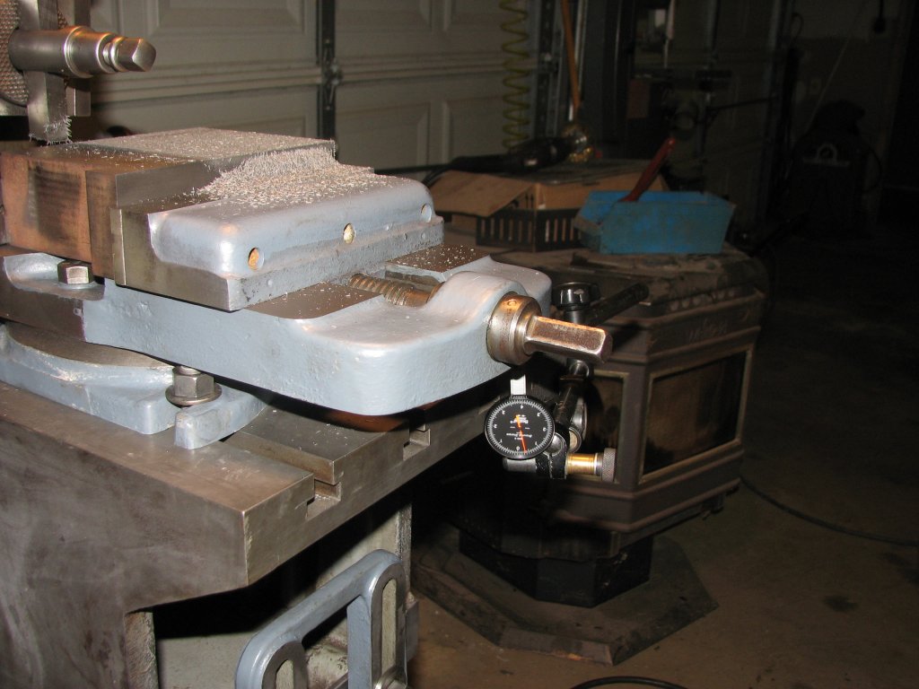
| This is
my attempt to measure flex in the over-hanging section of
the vise body. |
Instead
of flex, I am probably reading the machine rocking and
need to bolt the shaper to the floor. |
Early in the
process of working on this shaper, I put up a picture
of a shaper vise that had a pair of bosses to support the rear
section of the vise. I thought it looked like a good idea to
reduce flexing of the vise body. I decided to try and measure if
there was any flex when taking a light cut. I mounted the DTI
magnetic base to the side of the table and placed the stylus under
the vise. I then cut the surface of the test block again. What I
saw convinced me that I need to bolt the shaper to the floor. The
DTI needle was bouncing between about a half and full thousandth.
I took a couple pictures that seem to show that there could be
some flex, but I don't think that's what the DTI is showing me. It
is more likely that the needle is bouncing due to the fact that
the shaper is rocking on each stroke and the DTI needle is
bouncing rather than reading flex in the vise. I won't be able to
confirm this until I secure the shaper to the floor.
Time to wrap up
this installment. I am close to accomplishing the goals I set when
I took my first cuts and found that the shaper wasn't as accurate
as I had hoped it would be. I think I have been successful in
helping this shaper produce a little more accurate work as well as
taking care of a couple problem areas that I found. The shaper now
runs as I figure it should and produces fairly accurate cuts. The
next projects are to bolt the shaper to the floor and to try and
recreate the missing ball handle that is used to lock the ram
position. As far as the ball handle is concerned, my shaper
currently has a single nut in place of the missing ball handle. I
posted a message on the Yahoo Metal Shaper group asking for the
dimensions of the handle and a nice gent in Washington state
supplied me with the information I needed. All I need to do now is
to build the radius turning attachment for my lathe so that I can
make the ball handle. Sounds like fun to me.
| Shaper 1 |
Shaper 2 |
Shaper 3 |
Shaper 4 |
Shaper 5 |
Shaper 6 |
Shaper 7 |
Shaper 8 |
Shaper 9 |
© Fager November 9, 2015