
|

Grizzly
G3103 Repairs - Part 2
April 03, 2010 through June 11, 2010
When we left off,
the saddle had been surface ground to get rid of the somewhat less than
marginal job of fitting that had been done at the factory. It
looked like it was performed with
jack-hammers and angle
grinders. Now I was able to use the saddle as one scraping template,
along with a
24" granite angle template. The granite angle template was cut
from a 18" X 24" import surface plate on a wet saw modified to run a
12" blade and lengthened to allow a 24" slab of granite to fit on the
rolling table. The 3" X 3" X 24" piece of granite was then cut to
a 45° angle along one 24" face and then flattened on the surface
grinder using first a 150 grit, then an 800 grit diamond wheel.
This brought the
surfaces within a couple ten-thousandths of an inch of being
flat. Final finishing was done on a dedicated - for lapping only
- surface plate sprinkled with diamond
dust. The templates indicate to about a tenth variance between
adjacent
areas and a couple tenths over the entire length of the template with
checked with my shop made planecator copy, but this is in a non-clean
room, non-temperature controlled environment. What the actual
tolerance works out to is a mystery, but they seem to be as flat as my
36" Microflat granite straight edge. I've made a few for friends
and a few for myself and am
pretty pleased with both the flatness and the finish I
was able to get on these angle templates. Having an angled
surface template
is the only way to reach the hidden area beneath the dovetail section
of the
mill's ways. Having the angle at 45° means that the templates
will work
on most any dovetail way and having a pretty sharp point on the vertex
allows the template to reach into smaller dovetail ways, like those of
my South
Bend 9" lathe.
Working with both
the saddle and the angle template, I continued finishing the Y ways on
the top of the knee. At this stage, I had the angled knee Z ways
finished so that the knee now runs parallel with the column Z ways and
the knee flat ways were scraped to a point where the knee flat Y ways
were
almost exactly 90° from the column flat Z ways. Well, at
least the right side was about 90°. The left knee Y way
tilted down on the crank end of the knee by about 0.0025". The Y ways
also needed a bit of adjustment to their height. The left way was
higher then the right near the column, but lower than the right near
the crank end due to that 0.0025" drop in the left knee Y way.
My plan was to dial
in the right knee Y way so that it was level with the left way near the
column and sloped up toward the crank end by some amount greater than
zero and less than or equal to 0.0005". I also needed to making
sure that the left
way was as close to being an exact duplicate of the right as I can get
it. This meant scraping the right way to the proper angle, then
"scraping straight down" until the crank end was the same height as the
left. This was due to the crank end of the left knee Y way being the
lowest spot on that way. Once the right way was correct, I could
use the saddle with the box level on it as one means of helping me make
the right way match the left. Are you totally confused? I
must admit that it's hard to describe without pointing to the spots I'm
talking about.
 |
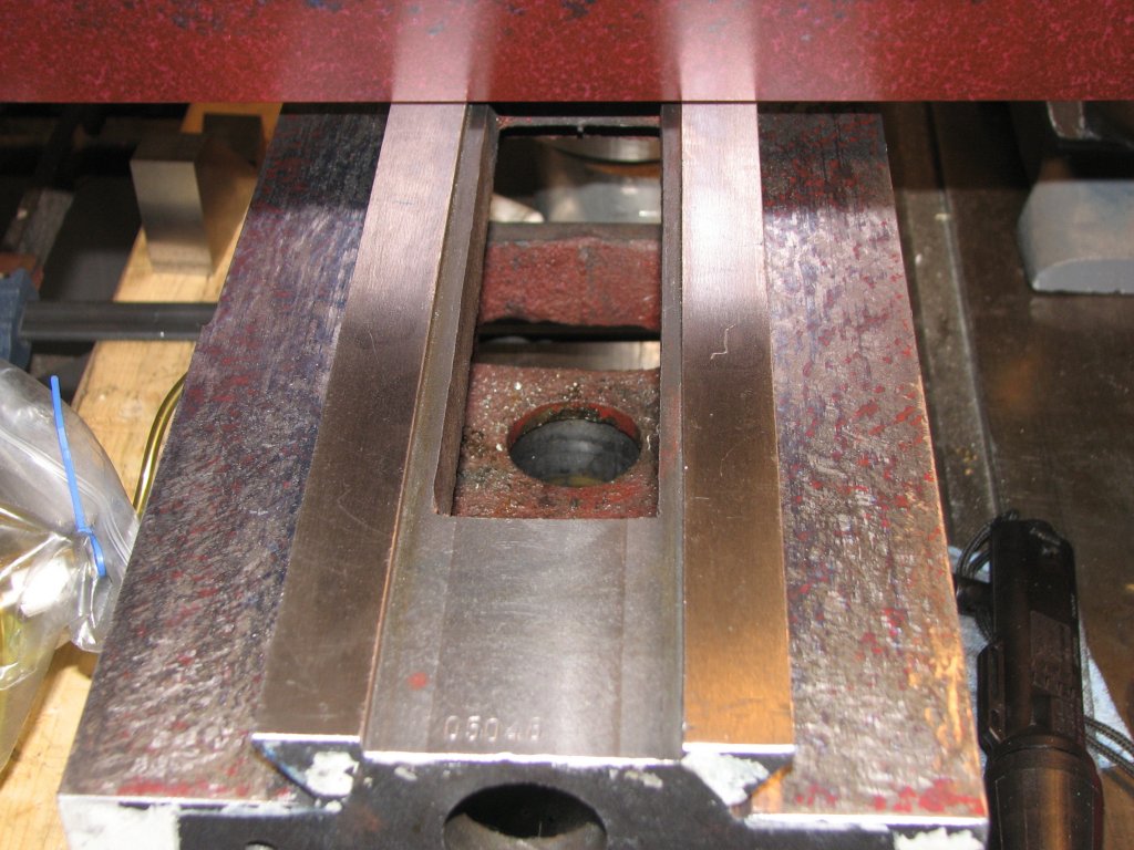 |
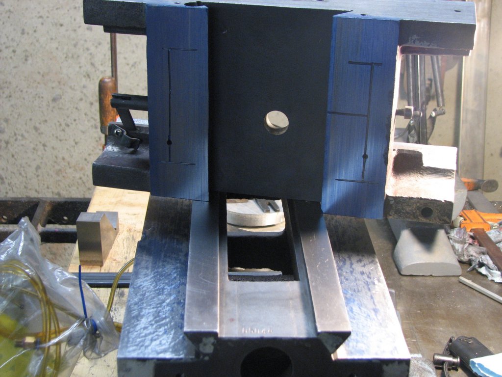
| Scraping
the
top Y ways of the knee using the saddle as a template to keep both
flat Y ways in the same plane. This is the first step. |
The
second
step is using my 24" granite 45° angle template to show the
high spots that need to be scraped in this cycle. Both templates are
required. |
With the knee
attached to the column, I used the box level with feeler gauges to
determine how much metal needed to be removed, then pulled the knee
back off and set it up on my work table. With the knee clamped
down to keep it steady, I rolled Prussian blue on to the saddle and
slid it along the Y ways. The tricky part is that while this
shows contact, it doesn't
show what needs to be scraped. The reason this is true is that
the saddle is shorter than the run of the Y ways. As the short
saddle is slid
along the long knee way, it can only leave a print in the area it
touches. If the long saddle way was high on the ends and low in
the center, you would only get two marks - one at each end of the
saddle. If you pick the saddle up and place it back on the long
knee way one inch to the right, you would have two different
marks. It
doesn't take much imagination to see that you could have solid color
for the entire knee way and still not know where the high and low spots
were. However, if we use a longer template to mark a shorter way,
we see the true picture of the ways. (As long as our template is
flat.) I found out through trial and error that using a
template shorter than the ways, even by an inch or two, makes it more
difficult to scrape the way flat. On my surface grinder, I used a
36" template on a 40" way. It can
be done, but it makes it a lot harder to get the way truly flat. It is
tough enough to get a way to "tenths" of flatness without handicapping
yourself with a too-short template.
So, after marking
the pattern of contact with the saddle with blue, I
then used Dapra water soluble red marking fluid on my 24" granite
angle template and printed over the top of the blue prints. I
would scrape all of the red marks and try to get more and more blue
coverage on each consecutive cycle of printing and scraping.
Since I was again trying to change the angle of the ways in two planes,
I used a progressive method of scraping. You start by dividing
the length of the ways into equal one to two inch sections. Next
you print the entire way with color and scrape only the section on the
end you want to be the lowest. When you finish that section,
you clean the way and print it again. This time you scrape
sections 1 and 2 of the low end. This is repeated until all
sections have been scraped. If I feel I am close enough to the
finished angle to take some measurements, I then print and scrape the
whole way in one pass a couple times to get rid of the steps I've made
by scraping individual sections. Then I take my
measurements. If I know that I am not close to being ready to
measure, I repeat the step scraping technique until I am ready to
measure. Using the Biax power scraper, the step scraping goes
quickly and each complete cycle of steps may take off 7 times as much
metal from the low end as from the end that will be higher, so the
angle of the way changes fairly fast. To increase the angle of
the way more quickly, I go over each step a couple times, scraping in
different directions. Scraping in different directions not only
removes more material due to repeated scraping of the same area, but
also makes it easier to see what was scraped on the last pass versus
the current pass. Last, but not least, scraping in different
directions helps prevent the forming of ridges/ripples in the grain of
the metal that happen if a piece is scraped repeatedly in one direction.
Last night's
progress was pretty typical. In about two hours, I lowered the
column side of one way by about 0.002" while I continued to scrape for
bearing points on the other way. Scraping for bearing (picking
the tops off of the high spots) takes a lot more time than running the
Biax over areas of color to change the angle of the way. And yes, even
after scraping almost every day since January 24, I still get sore
arms, a sore back, too.
I'm getting closer
to having the Y ways of the knee level in all planes. A couple night's
work brought me within a half thousandth on an inch side to side
"height" of the Y ways. The right way is about a quarter of a
thousandth high on the crank end (perfect), but the whole way is still
a half thousandth high. So, I have the angle right, but need to
scrape down a couple more passes to make the box level sit level when
straddling the two Y ways. I check this measurement by placing
the box level on two 7/8" precision shafts; one on each way.
 |
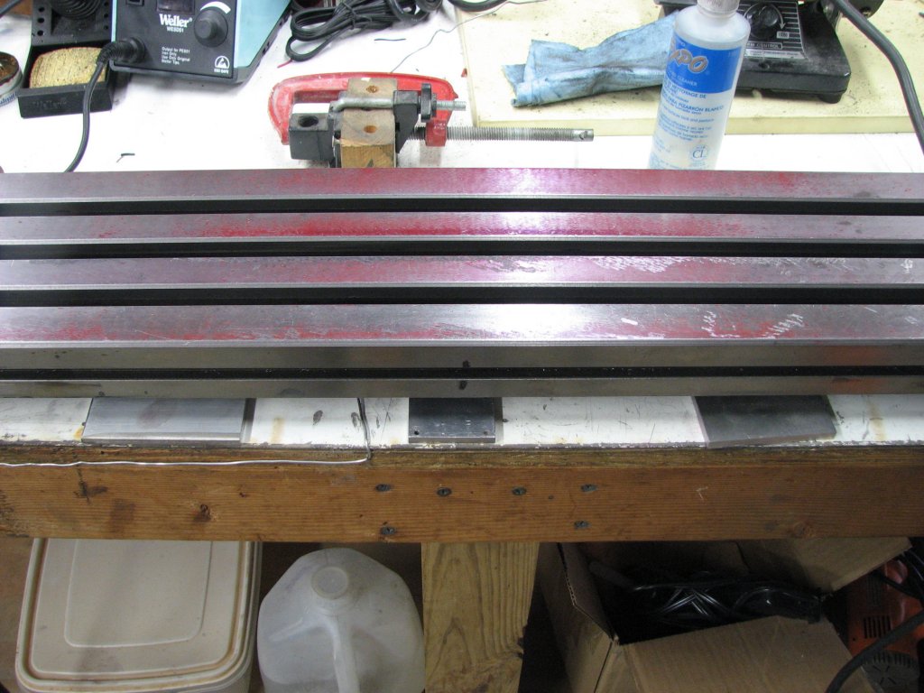
 |
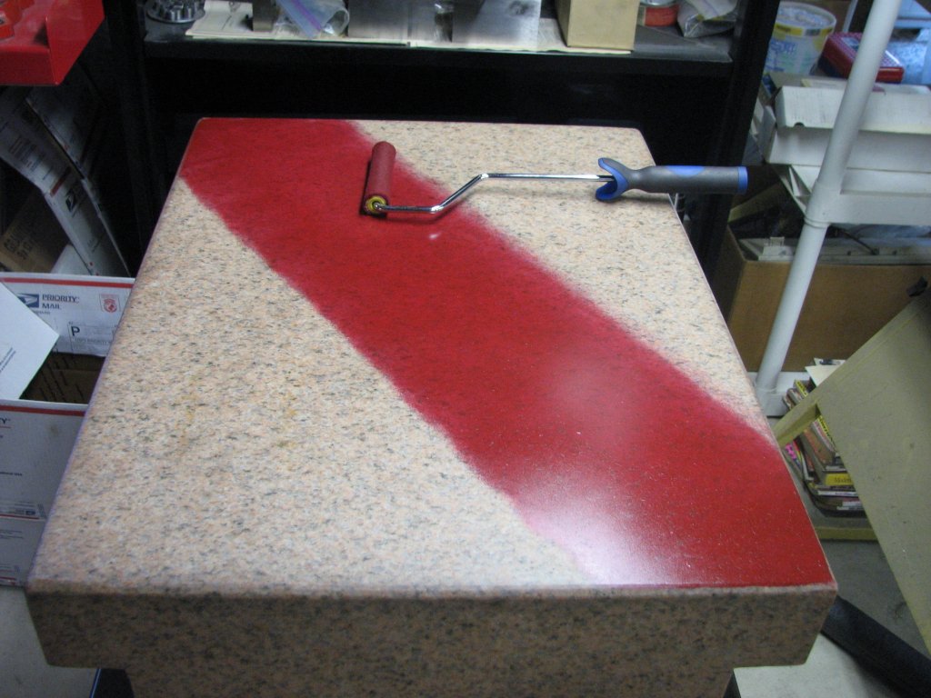
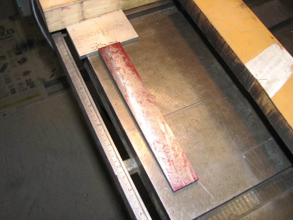
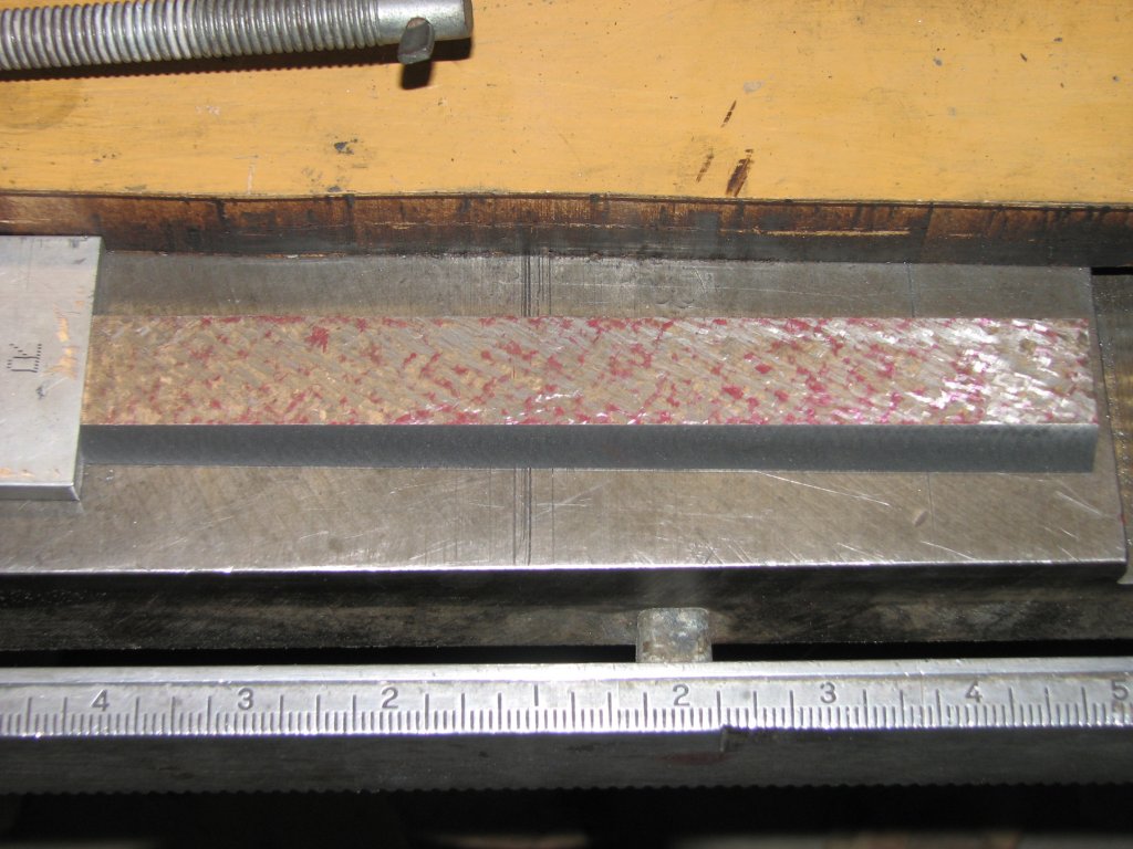
| Using a
short nap roller, I rolled out some water soluble marking fluid.
Rolling diagonally, I was almost able to mark the whole table |
The corners
of the table are off the surface plate, but there's enough contact to
give me a good print of the majority of the table. . |
 |
 |
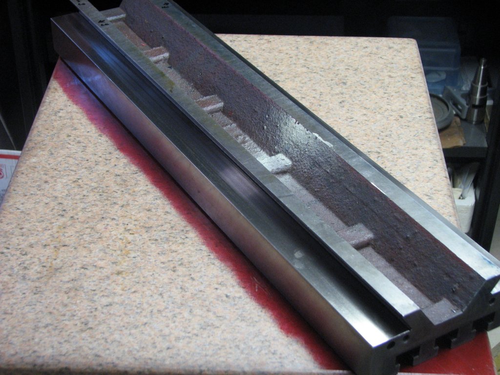
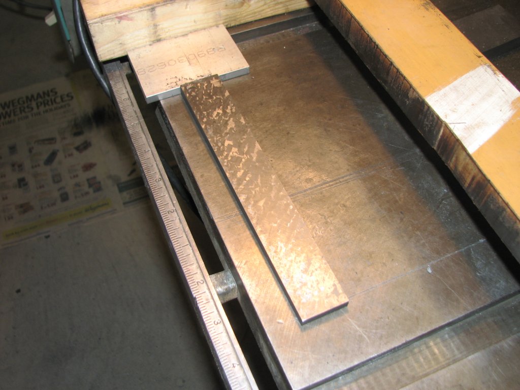
| This
is
the print made by my largest Starret surface plate. The table
is a little high in the center and has a slight warp. Scraping will
even out the surface. |
By
alternating
between the 24" surface plate and the 36" long template, I
can scrape the 26" long table flat. Next I'll scrape the table
ways. |
Another couple of
night's work had the saddle sitting plumb on the knee. I was from 0 to
0.0005" from flat in every direction according to my box level. For the
time being, I stopped scraping the top of the knee and started on the
table. I blued (redded?) up my largest surface plate on the
diagonal and
printed the top side of the table. There was a little twist in
it, but not terrible. I considered surface grinding the table.
but at 26" long, it is as long as the travel on my grinder. I could
have disconnected the hydraulics and manually fed the table to get
enough room for a 1/4" run-off in either direction, but the more I
thought about it, the more I thought that a scraped surface on the top
of the table would look cool. I ended up scraping. It took me two
4 hour sessions to get the table to 20 or so points per square inch and
I stopped there. Going for surface plate quality scraping was
over-kill. The table is always accessible, so if I feel the need
to produce a finer surface at some time in the future, all I have to do
was scrape. No disassembly required.
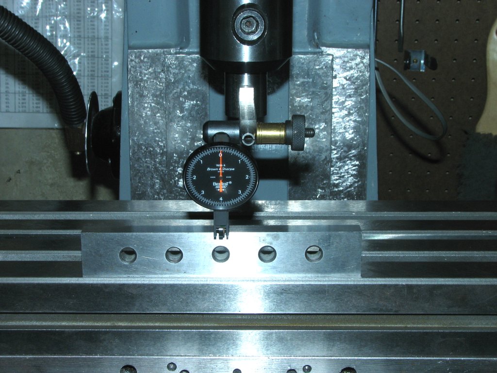
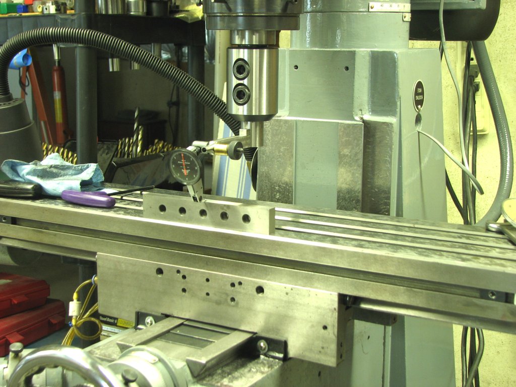
Using my B&S
half-tenth indicator, I measured the height of the ways from the
surface plate. The ways were out by about 1 and 1/2 thousandths
on opposite ends. The front way was high on the right and the
rear was high on the left. I found the lowest point of the two ways and
set to scrape both ways to that height. Scraping dovetails with a
Biax is an art. One that I haven't completely mastered yet.
You need to have pretty near perfect control of the tip or you run into
the opposing angled way. So far, I've found the
easiest way to scrape the last bit before the vertex is to sneak up on
it. I start scraping with light pressure well before the crucial
section and slowly advance at an angle until part of the carbide tip
hangs over the channel that's cut into where the two ways join.
With the blade half on and half off the way, I travel down the edge
applying more pressure when I encounter marking fluid.
After a few cycles
on both of the tables X ways, it was back to the surface plate to check
the height. This went on for about a week of evenings until I was
within tenths of having both ways parallel to the table top. About once
an evening, I would blue the X ways of the saddle, then lift the table
on to the saddle and install the gib. I'd test for proper
tightness of the gib, then place the box level on the table and push
the table from end to end while noting the bubble in the level.
Each night it got a little better and the bubble stayed centered over
more of the table's travel. Each time I removed the table and
checked the blue marking, it was covering more and more of the
ways. This was satisfying, as I could see my progress improving
and the better the markings got, the more I wanted to scrape to get
them even better. I also began making marks on the table
indicating where the gib was tightening up and where it was loose as I
slid the table from side to side. This would help when I started
scraping the angled ways of the table.
I again checked and
made a couple adjustments to make sure the mill was level. I did
a
few more test fittings and a little more scraping. I was about
finished with the major scraping. I had never really liked the
cream colored paint on the
mill. It shows every dirty fingerprint. I had also chipped
the paint in a number of places while taking it apart for the many
fixes I'd performed over its short life. I wiped down the base
and column with acetone, then sanded them with 500 grit wet and dry
paper. I brushed on a few coats of Rustoleum gray. I decided that I
liked the color on the mill, so I got to work cleaning masking and
painting each of
the parts. I figured since I had it in pieces anyway, now was the
time to give the mill a cosmetic update.
April 21, 2010
I've gotten the painting under way. While various pieces are
drying, it's time to do the final way scraping. This involves cleaning
up
the 55° angled ways so that column, saddle and table intersect at
as close to perfect 90°
angles as I can get. On this particular mill, this is
easier said than done. The present goal is lining up the table
slots with the table's rear angled way. In a perfect world, the
outside perimeter that makes up the table would be parallel/square with
the T-slots and the rear angled way. The front angled way is not
meant to be parallel with the rear as the angled way and its gib are
wedge shaped in order to adjust for wear. In the real world, on
this mill, none of the surfaces; rear of table, angled way and T-slot
are parallel. Close, but not close enough. So the task
becomes aligning the T-slot with the rear angled way. Forget the
rear surface of the table altogether as it really has no bearing on
clamping work to the table and milling it square. As long as the
T-slot and rear way match and end up at a 90° angle to the Y axis
and parallel with the surfaces of the Z flat ways, we will be set.
To check the table
for parallelism, I placed the table on the surface plate with the front
surface down and the rear way on
top. I shimmed the table until I could measure a constant
distance between the surface plate and the T-slots. I will say
that all three T-slots were all very close to parallel with each other.
I then clamped a 1/2" piece of precision round stock against the rear
angled way and measured between the round stock and the surface
plate.
The left end was high by a little under a thousandth. Not
bad. I scraped the angled way until the measurement was the same
across the entire way. To ensure that I kept the way angle at
55°, I used my 13" cast iron 55° angled template. To make
sure that the way remained in one plane, I alternated with my 24"
granite angle template.
With the T-slots
aligned to the table, the next step was making sure that the
T-slots were at a 90° angle to the saddle, the saddle is parallel
to the knee and the knee is 90° to the column flat ways. The
knee to column fit should be darn close, as I had already scraped the
flat Z ways of the knee to align at 90° in both the horizontal and
vertical planes. The adjustments I'd be making now to the angled
ways on each of the axes not only ensure that the flat ways contact
tightly, but are also a constant distance apart from each other. The
angled ways need to be scraped so that when the gibs are installed and
the cranks are turned there is no binding or looseness. However, since
my current gibs were an amalgamation of cast iron, sheet aluminum and
steel feeler gauges, I figured I ought to make some proper gibs first.
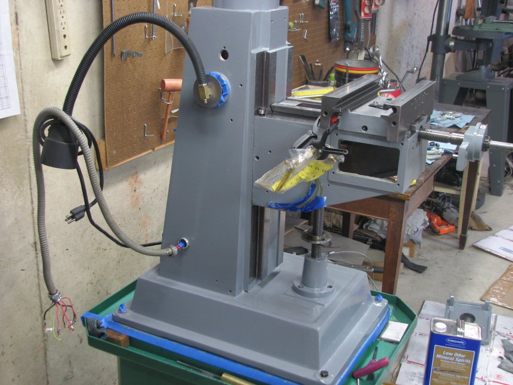 |
 |
| Reassembly
begins |
I
like
the
Rustoleum
gray
on
the mill. |
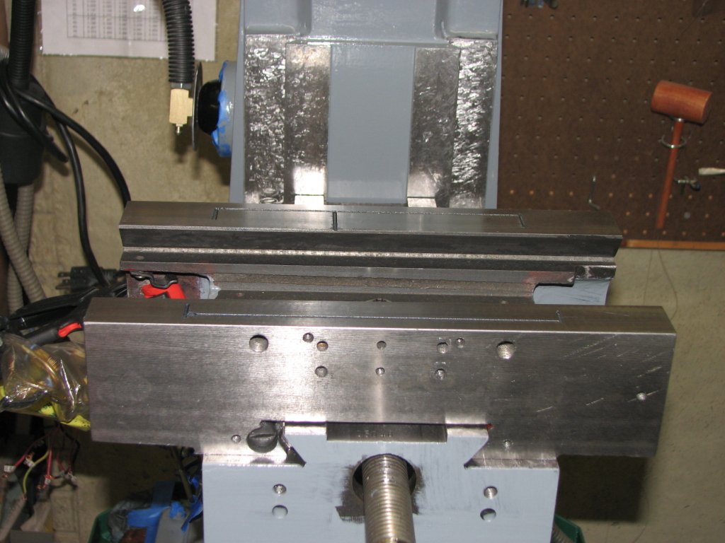 |
 |
| The
temporary
gib
is
installed. |
The
"T"
connection
is
bolted
up. |
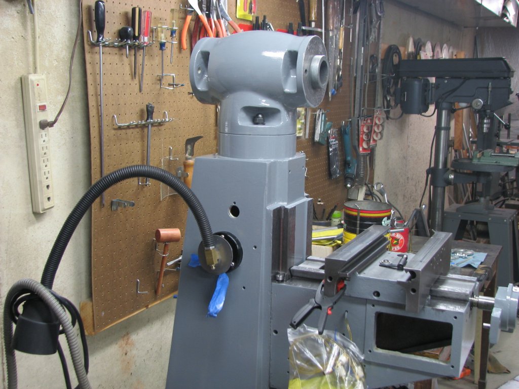
 |
 |
| The
milling head gets attached. |
Two
of my buddies watch my progress. |
I reassembled enough of the mill that I could actually make some test cuts. I was most interested in whether the X and Y axes were square - I.E., the table square with the saddle. I chucked up a 2" by 8" piece of cast iron and machined the 8" length along the X axis. I machined both ends at a 90° angle. I then removed the work and placed it on my surface plate. I used my 8" square to check how close I was able to machine the angles. Using the shimmed gibs on both the saddle and table, the block came out pretty square. Certainly a lot better than it had been. I measured about a half a thousandth between my square and the top of the cast iron. So that's a half thousandth with a 2" by 8" piece with shimmed gibs. I wanted to take another couple of cuts on a larger piece of steel to get a better opinion of the squareness, but in setting up the steel to be cut, I noticed a bit of looseness in the table. I set a DTI in a collet and tried pulling and pushing on one end of the table. I had a couple thousandths of play.
I decided i should go ahead and make a proper gib to tighten up the table as well as one for the saddle. The shims I had added to the gibs amounted to a shim of one thickness at one end and a different size of feeler gage at the other end. This meant that there was not much contact between the two ends and this would have some effect on the final fit of the saddle and table.
I used my shop set of gage blocks to take the measurement of the space where the gib would fit. I did this by shimming the gib a little too thick to check the small end. This wedged the ways against the gib without allowing the gib to travel all of the way to the end of the space where it normally sat. I then used the gage block to measure the distance between the two ways. I added 1 thousandth to my measurement to make sure that the gib would be a hair too fat. I would scrape off the excess.
I
then shimmed the gib a thousandth or so too thin and reinstalled the
gib. This would make the gib run too deep in its home and free up the
large end for measuring. Again I used a combination of gage blocks to
find the thickness that the gib should be. Again I added a thousandth
for scraping.
 |
 |
| The
slope
of
the
gib
has
been machined and the gib surface, both front and back,
is pretty flat. |
Both
sides
get
scraped.
The
back
side doesn't need or get as many points per
inch. |
 |
 |
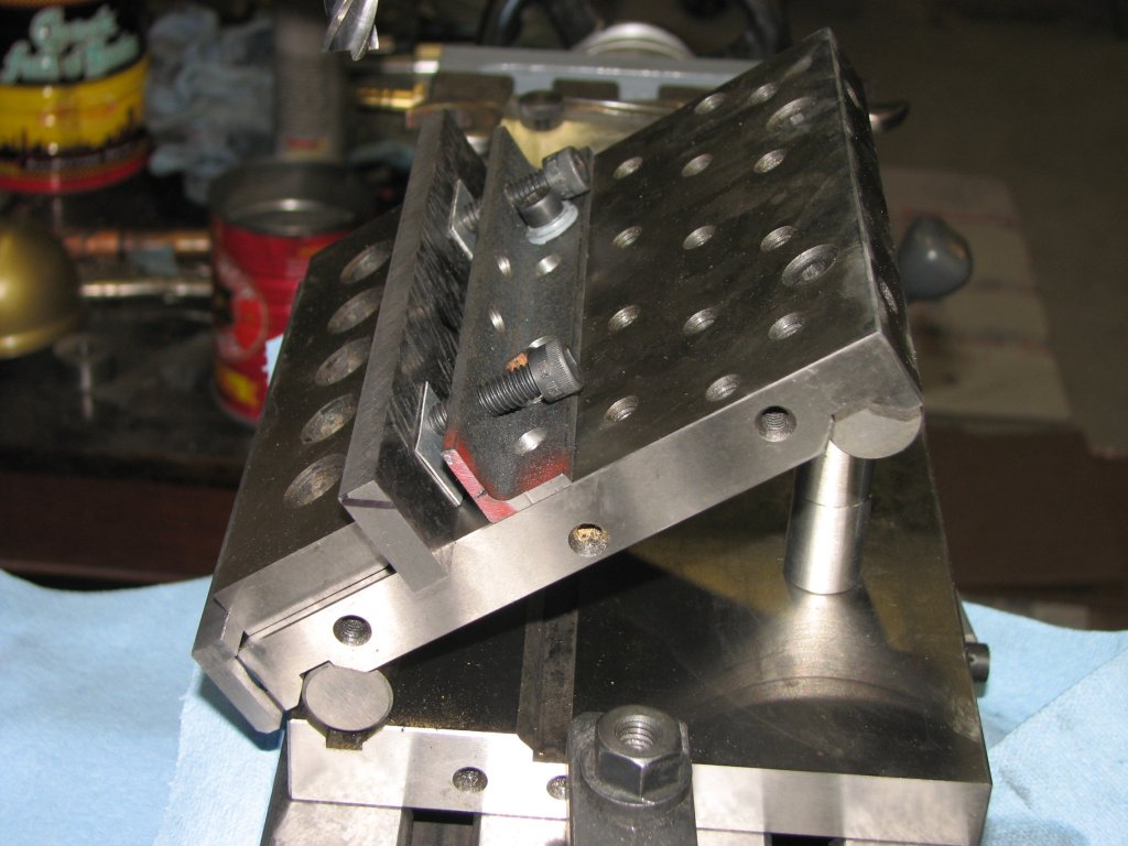
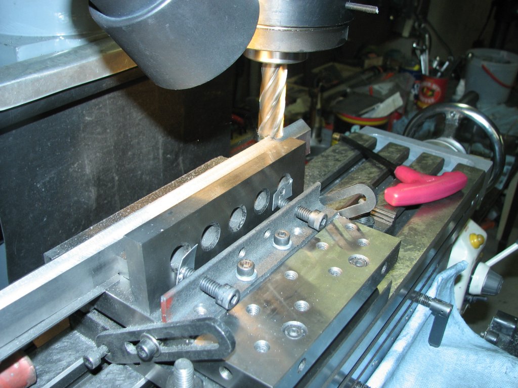
| The
sine table is is set to allow a 55° cut. |
The
print is beginning to fill in nicely. |
The saddle gib is 6.125" long and the thick end measured .375". the small end was 0.090" smaller at 0.285". I divided 0.090 by 6.125 to get the taper per inch and multiplied it by 5 to get the measurement to set the slope of my sine plate. I used some 1.125" X 0.50" by 7" cast iron stock and cut the slope angle. I then cut the two angles to turn the end view of the gib from a rectangle to a parallelogram. The Grizzly mill uses a 55° angle on the angled ways and the gib obviously should match this.
Once
I had an overly long copy of the gib,
I used some black permanent marker to
color the side of the gib that touches the sliding way. I oiled up the
ways and installed the gib. I moved the axis with the
new gib enough to wear away some of the black marker. I removed the gib
to check it. Since it appeared that the gib was contacting a bit more
on the small end than the large end, I did some scraping on the small
end and tried again. After a couple attempts, I had pretty even contact
on the gib, though it was still a little thick and did not seat all of
the way into its home. Some more scraping fixed that. I now had one gib
that fit well, but was a little long on the large end. Since that extra
length was my adjustment material, I decided to cut the gib a little
on the long side - just in case. The new gib ended up at 6.625" instead
of 6.125". Having the extra material on the large end caused no
problems and would possibly save me from having to machine another gib
if I needed to scrape a bit off the ways to adjust for squareness
before I was finished "tuning up" the mill's ways.
 |
 |
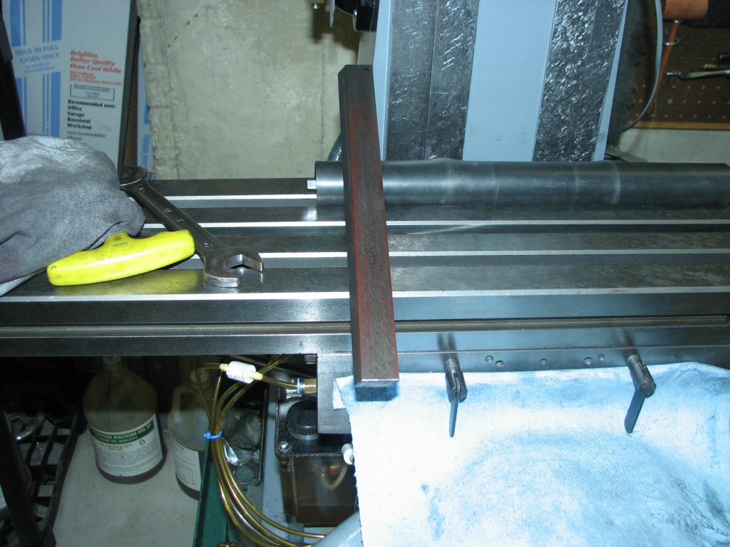
| All
three gibs were made the same way, but the third one was charmed and came out perfect. |
A
lot of overhang and the parallel lifted a bit, but the 55° cuts matched the ways perfectly. |
 |
 |
| It
was nice to use the mill again after many months of being without it. |
The
finished Z gib after being fitted. The marking fluid was rubbed off evenly showing that it fit well. |
I moved on to the long table gib. It's a little over 11 inches long and I had a piece of cast iron already cut to 12" inches and scraped flat on one side. I had cut this to size and scraped one side flat a couple of years before as I was going through the long process of acquiring the necessary tools and experience to strip and scrape the mill.
I made my measurements in between interruptions of folks coming to our house to adopt some kittens. This turned out to be a mistake. Over the next couple nights, I set up and machined the slope and two 55° angles of the gib. I finished it and gave it a try. It only went about half way into the slot before it stopped. After some head scratching and remeasuring, I discovered I had machined the thick end wrong. It was exactly 0.050" too thick. Lovely.
Five
hundredths is too thick to scrape. Especially when only one end is that
much too thick and the other end is dead on spec. I'm sure it could be
done,
but it is something that would take a lot longer than just making a new
gib. Since I had already machined the 55° angles into the gib, it
would be very tough to hold in my large milling vise. I decided that
the repair technique that made the most sense would be to use the
magnetic chuck on
the surface grinder. I would put the old gib, shims and all on the
table, then the new gib on top of it in the opposite orientation. I'd
then build a wall around the two stacked gibs so that they wouldn't
wander off. The magnet in the 24" chuck is pretty strong and should
hold everything pretty firmly. The built-up wall would prevent the shim
from
launching itself through the shop or me. When the gib was within a
couple thousandths of where it should be, I'd finish it by scraping.
As
it ended up, I was too concerned about grinding the gib too small and
left it a few thousandths too thick. It took a few nights to
scrape it to the desired thickness. The most important
consideration I had was that I get the thickness right on the small
end. The small end of the gib fits into the right side of the
table and this was where I had a couple thousandths play. When I
finally had even wear marks in the marking medium I used on the gib, I
cut the gib about a half inch too long on the thick end. Again,
this would allow me some adjustment if I needed to do any scraping on
the angled ways to align the table.
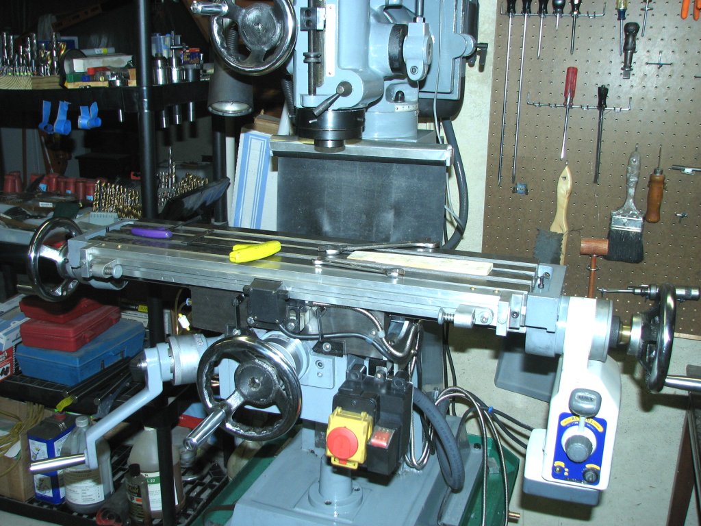
Even
though I still had some "tune-up" work to perform on the angled ways to
get the mill as square as I could get it, I was impressed with the feel
of the three axes. The X axis of the table was especially
nice. Prior to scraping, the only way I could get a smooth feel
when cranking the table from end to end was by loosening up the gibs to
the point of introducing too much play. Now with a DTI
in the spindle resting against a block on the table, I could give a
strong push and pull near the table ends and see a total deflection of
a little less than 0.001". Before scraping the mill, I couldn't
even get close to a
thousandth deflection with both table locks cranked tight.
I was now getting anxious to finish the mill and work on some projects
I have been wanting to do.
I
was now coming to the final stretch of this project. All of the
ways were scraped close to where they need to be. I could finally
start checking and setting the last adjustments. The first thing
to check was making sure that the end mill was being held square with
the table. The usual method for this is called tramming the
mill. This is nothing more than using a dial test indicator to
check for squareness between the spindle and the
table. Since the G3103 mill has a table width of only 6 inches, I
use a extension that is 3 inches in length. My extension is a
1" diameter piece of drill rod with a 1/4" by 1" piece of flat stock
attached at the bottom of the round rod to form an L shape. At
the end of the flat bar is a provision to hold my half-tenths-reading
indicator.
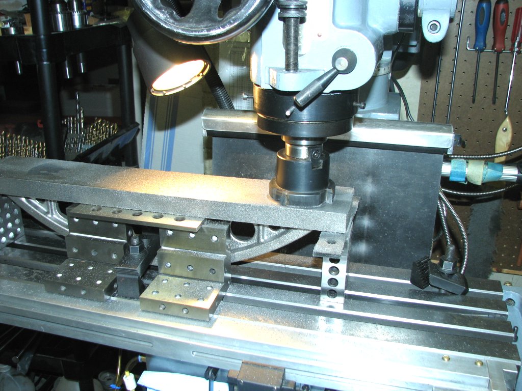
The
procedure is to eyeball the milling head to align 90° to the table,
then install the indicator and holder. Using a known flat half
inch wide parallel between the indicator tip and the table, I bring the
table up to find zero on the indicator. Starting with the
indicator pointing at me, I slowly hand-turn the mill's spindle in a
full revolution. I move the parallel so that it stays centered under
the indicator tip as I move the indicator in a full revolution around
the spindle. I note the relative height of the indicator a each
quarter revolution. The readings at the 3 and 9 o'clock positions
should be the same if the table is flat and square in the longitudinal
axis. If the 9 o'clock reading is 0.003" high and the 3 o'clock is 0.003" low, then
the milling head will need to be revolved counter-clockwise to make
both measurements zero.
 |
 |
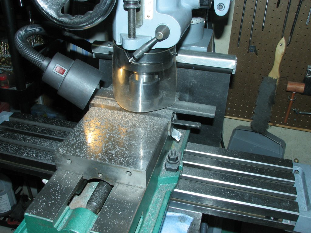
| To
tram the mill, I started by bringing the table up until the DTI read
zero and locked the knee. I then took measurements every 1/4 turn of
the spindle. |
Another shot of using the parallel as a spacer between the table and DTI.
Using the parallel also helps to bridge the T slots in the table. |
I
set the mill head to be level along the length of the table - 3 and 9
o'clock positions. Unfortunately,
the G3103 doesn't have an adjustment to change the tilt in the 12 and 6
o'clock positions, like the Bridgeport "nod" feature. If this
plane is out, all that can be done is to scrape one of the junctions
between the milling head and the column. If all else is equal, my
choice would be the junction at the top of the column that allows the
head to rotate around the column. However, I had started this project
by scraping this junction square with the column ways and then tried to
line up the spindle axis with the flange on the milling head, but fully
expected that some adjustment would be needed. It was. I had
about one and one half thousandths difference between the front of the
table and the rear as I revolved the indicator. As the rear
(column
side) of the table was indicating high, I scraped a small amount from
the bottom of the vertical front flange junction to lower the front of
the
milling head a bit. By lowering the front, I was also raising the
rear where the indicator was reading that the table was high.
This was a real pain to
do as it required me to disassemble the milling head and pulley covers
to gain access to the flange. I got lucky and only had to test
fit a couple of times before I had less than a half thousandth
difference between the front and rear of the table. Seeing as the
measurement I was taking was three inches from the spindle and my
indicator showed less than 0.0005" between the front measurement and
the rear, I think that most of my end mills and face mills, which only
go to three inches in size, will cut true.
With
the milling head trammed, I ran the table to the ends of its travel and
checked the measurements. Since this is a lightly built mill, the
weight of the table pulling down on one side of the saddle causes a
little drop when the table is near the end of travel. This is
amplified because I have extended the travel by about an inch on each
side. The drop at the end of travel amounted to a little over
0.001". The drop isn't something that I will encounter in most of
my projects since I generally work in the center of the table, but when
taking a cut of a foot or more, I will need to remember that it will
cut a bit deep at the table ends as the other end of the table will be
drooping a bit.
I
keep thinking about how long I have been working on this mill. In
the early stages, I tried to follow the plan I had set, but it was hard
to judge what kind of progress was being made. Now as I get
closer to finishing the project, I'm able to make some observations of
what has changed. Cranking the handles on all of the axes
is much easier now. The ways slide very smoothly. The knee
and saddle locks now clamp down on the gibs and lock up more
positively. The settings don't wander as much when locking the
axis as they had. Best of all, I can place my box level on the
table and crank the mill on all axes and have the bubble stay fairly
well
centered. Not perfect by any means, but before rescraping I
couldn't even get usable readings on the 0.0002" per increment box
level. I had to use the much less sensitive level and the
bubble moved all over depending on which way I cranked. All in
all, a great improvement in the accuracy and feel of the mill.
Now that everything is back together, I took a test cut on a small piece of cast iron. I side milled the length along the X axis, then carefully re-clamped the right end without moving the setup and made a cut along the 4" side at a 90° angle using the Y axis. I removed the cast iron and set it on the surface plate along with my L square and master square. The 90° angle between the short side and long side are darn near perfect - or at least as close as I can measure to perfect. I repeated the test with a 12" X 4" X 1.25" thick piece of cast iron. Again, the results were as I had hoped. The end cut was square with the side cut.
The
last piece to do was to make a new Z gib. I have been using a gib that is made up of a number of shims and the old gib and it's time
to replace it with a proper gib. The 12" X 4" piece of cast iron
will be sliced and a new gib made.
I
cut a 0.450" slice off the bar of cast iron, then machine the cut side
flat. I scraped the 12" X 1.25" surface enough so that there were
no obvious high spots. Since this axis had been modified a bit by
cutting the knee right side angled way a bit deeper at the bottom, I
remeasure the shimmed gib a couple times and measured the space it fit
extra carefully. I had 0.077" taper over 8.125" inches of
gib. I divided by 8 and multiplied by 5 to get the settings for
my 5" sine bar. I then used my 6" machinist's vice to hold the
sine bar and 12" gib. The gib was left unsupported, which I
suppose is a bad thing, but I planned on only taking 0.005" cuts.
I figured that deflection would be minimal. Once I got the slope
of the gib machined, I set up my 6" sine table to machine the 55°
bevels on the top and bottom of the gib. These end up being a
compound angle cut to keep the face of the gib a constant size. I
did the math for the depth of cut then checked the face for size as I
machined the 55° angle. Once the gib was cut, I did a real
quick bluing and some preliminary scraping. I really wanted to
try it and see how close I had come. I was concerned that I might
have made an error in my calculations. No error. This gib
fit almost perfectly without any more scraping. Of course I
scraped it anyway as the surface I got from milling it wasn't the best,
but I sure hit the milling measurements right.
With
a properly adjusted gib in the Z axis, I once again checked the level
of the table. I was a small amount high on the right side. Less
than a half thousandth. I figured that this might happen when I
finally got a proper gib fit. Unfortunately, this meant that the
table and saddle had to come off again so that I could scrape the top
of the knee back flat and level. I've had the table and saddle on
and off so many times that I could do it blindfolded.
I
lowered the right way of the knee and adjusted the left way so that the
saddle made good contact on both ways. I checked my progress with
the box level and stopped when the bubble moved less than 1 increment
in any direction (0.0002" per 10"). I am still pretty amazed that
I can crank the saddle forward and back and have the bubble not move
more than 1 division. Yes, it's supposed to be like that, but
until now it's never been even close to level and this is a real treat.
 |
 |
| One
of the last pieces to install was the guide for the power feed stops. The DRO scale is hidden behind it and covered with some aluminum sheet. |
The
first project on the rebuilt mill was taking some skim cuts off the bottom of an 18" camel-back straightedge casting. |