
|
Why Heat Pipes?
A few years ago, the prime overclocker's
processor was the Celeron 300A. At its stock speed, the processor
generated about 18 watts of heat. If you were lucky enough to get one to
run at over 500, it would generate about 30 watts. We routinely attached
dual-fan heat sinks like the Alpha P125 with its huge dimensions of 4.8
x 2.1 x 2.3 inches (120 x 55 x 60 mm) which did a great job of keeping
these puppies cool. Now we have the Thunderbird at 1.2 gigahertz
(stock speed) producing up to 66 watts and we are trying to cool it with
a heat sink of about half the size of the P125. If you add to this
the fact that the contact area of the processor has shrunk to 1/4 of the
size of the Celeron's, you'll see that the challenge of keeping the processor
cool is becoming more difficult.
While after-market heat sinks are becoming more and more sophisticated in their design, there comes a point where there's only so much you can do with a hunk of metal and a fan. For a heat sink, size (surface area) matters. Given the ever shrinking area that our heat sinks must fit in, "alternative" cooling methods such as water cooling and heat pipes become a much more attractive method to "get the heat out."
I have gone the water cooling route and have been very pleased with the results. I have now had a water cooler on (at least) one of my computers continuously for a year and a half. Once I was able to get past the condensation problems, I have had no problems or failures. However, water coolers are not for everyone. So, as one who tries to be "forward thinking" and likes to always have at least one project going, I have turned my thoughts to what I consider a more elegant cooling solution. Heat pipes.
While heat pipes are fairly common in high-end laptop computers, their use in desktop computers has been limited to a few (from what I've seen) mediocre units. Tillmann Steinbrecher has a review of one such unit in the review he did for Anandtech; here. I think that as processor power (and heat) continues to increase we will begin to see more heat pipes used as a means to keep our chips cool.
Heat Pipes
As the story goes, it was in 1963 when
a Los Alamos National Research Laboratory engineer named George Grover
demonstrated the first heat pipe. Heat pipe technology was borrowed
from simple heat conducting pipes used by English bakers 100 years ago.
Since 1963, heat pipes progressed and modern applications of this technology
range from miniature heat pipes for cooling processors inside laptop computers,
to groups of half inch diameter and five feet long pipes that will be used
in NASA spacecraft, to pipes of two inch diameters (or more) which are
used to cool injection molds used in plastic forming. The lengths
of the pipes can vary from inches to 24 feet or more.
A lithium filled heat pipe developed at Los Alamos in the mid 1980s transferred heat energy at a power density of 23 kilowatts per square centimeter. If you consider that the heat emitted from the sun's surface is roughly six kilowatts per square centimeter, you begin to realize the enormous heat transferring capacity of the heat pipe.
How It Works
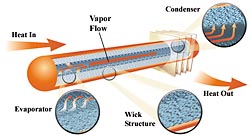 |
Heat pipes are generally composed of a tube, closed on each end, with fluid in it. One end takes in heat and the other expels it. The heat entering the "hot" end of the tube boils the liquid which turns it into a vapor. The vapor expands in volume and travels to the "cold" end where it condenses to a liquid and gives up its heat. The fluid is then returned to the hot end by gravity or a wick and starts the process again. The working fluid can be water in a negative pressure atmosphere or a fluid, such as freon, which is pressurized to maintain its fluid state.
Ideally there would be no temperature difference between the hot and cold ends regardless of what the rate of heat transfer is. However, there are physical limits to the rate of heat flow that can be transferred for a given temperature difference between the hot and cold ends. The heat must conduct through several interfaces and conditions. This includes heat transferred through varying thickness of the pipe walls, the thermal path of the liquid before it boils and after it condenses, and pressure differences between the hot and cold ends caused by aerodynamic friction. A professionally manufactured heat pipe can have a delta T as low as 2°F (1°C). However, with my rather crude building methods, I would consider a delta T of 10°F (5.6°C) a success.
The Project
The first step was to build a test heat
pipe to get a feel for how it would go together and what kinds of problems
I would encounter. Working the numbers and actually building a working
model are two completely different challenges. Often I find that
I don't have the equipment or technical prowess to put my ideas into working
projects and need to re-think the process. I wanted to make sure
I could actually build a simple pipe before investing the time in designing
a heat sink based on heat pipes.
For ease of building, the first project will use no wick and rely on gravity alone to return the liquid to the hot end. I decided to use automotive R134a "freon" as the working fluid. My decision was based on already having most of the necessary equipment to charge the pipe, the fact that R134a is somewhat environmentally friendly (read as not illegal like R12), and that the properties of R134a are pretty good for the purpose of a heat pipe. To get the R134a to a liquid state and have it "boil" at 80°F (26.7°C) I would need a working pressure of about 100 psia or about 85 psig.
psi = pounds/in2
psia = pound/in2 absolute
psig = pound/in2 gauge
psia = psig + barometric pressure
At 80 F, the specific internal energy for the gas and liquid phase of R-134a differs by about 70 BTU/lb. If we want to dissipate 100 watts, that would be about 29.3 BTU/hr. This means that we need to "boil" 0.42 lbs of R-134a per hour. That's 0.002 oz. per second. Depending on how fast we can get the condensed liquid back to the hot end will help determine how much liquid R134a will need to be in the pipe. At this point this is an unknown for me.
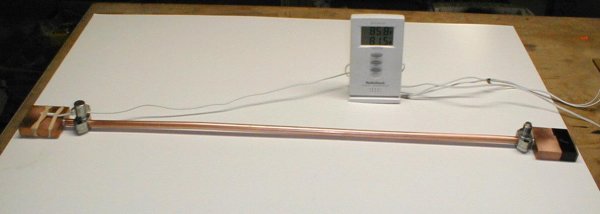
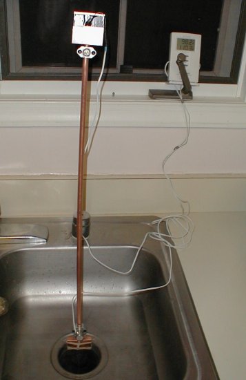
In building the first pipe, I hoped to
be able to find out if I could get the setup to hold pressure and if I
could transfer the heat a distance of two feet with some amount of efficiency.
The reason for the longish distance was that I eventually would like the
sink to sit on top of one of my full tower cases.
 |
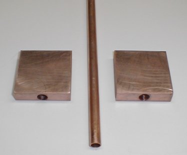
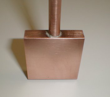
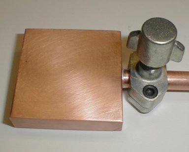
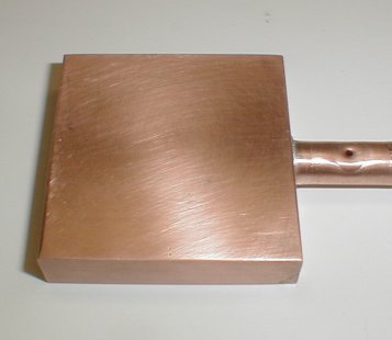
I got started by cutting a couple 2 inch
square blocks out of some 2" by 1/2" copper bar. Drilling in two
steps, I ended up with 3/8" holes that were 1 5/8" deep in each block.
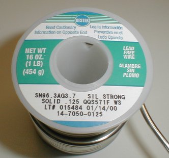
Using a torch and solder designed for use for refrigeration (3.7% silver
and 96.3% tin) I soldered up the three pieces. I then added to "service
valves" (1/4" flare fittings with a schrader valve) designed for R12 /
R22. The valves designed for R134a are too large for this application.
Note that you will have to use an adapter to connect the R134a can to the
R12 type valve.
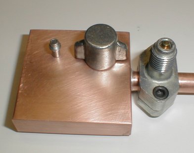
Note: Before soldering the second block, it is necessary to vent
the air inside the pipe to the atmosphere. I did this by installing,
then removing one of the service valves as shown below. If you don't
do this, the trapped air in the pipe will heat and expand. This will
prevent the solder from being "wicked" into the joint.
 |
 |
|
|
|
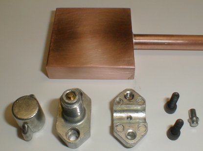
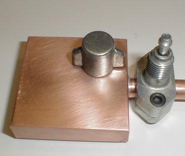
As I was having some trouble finding "screw
in" and "solder on" service fittings, I made the test pipe with "clamp
on" service fittings. While they are definitely not the best way
to go, they are readily available at many appliance service centers.
I did finally locate the "screw in" and "solder on" service fittings through
my local Aireco dealer
- a GREAT place if you're into refrigeration / HVAC - but it was too late
for this project.
 |
 |
|
|
|
 |
 |
|
|
|
 |
 |
|
|
|
 |
|
|
Once the test pipe was assembled, I faced
the task of filling it with R134a. After a few less than spectacular
attempts, I worked out a method that worked. There are probably many
better ways to accomplish this, but here is the method I used.
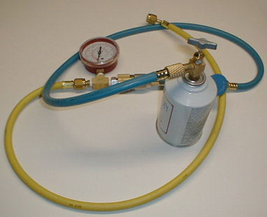 |
Warning: You will be working with compressed gas in a device of your own creation. Escaping R134a gas is VERY cold and will freeze skin quickly! Eye protection and gloves are a must. Body armor, a blast barrier, and having an idea of what you are doing are probably a good idea. Proceed at your own risk!
1. Put the heat pipe in the freezer.
The can of R134a and all of the hoses go in as well. The colder the
R134a, the less pressure you'll have to deal with when disconnecting the
hose from the pipe. This is a good thing when the volume of the heat
pipe is small as this is and you're trying to keep the R134a in the pipe.
2. After an hour or so, remove all of
the stuff and support the pipe vertically.
3. Attach the hose from the R134a to the
bottom fitting.
4. Attach a vacuum source to the top fitting
and draw as much of a vacuum as possible. This will also draw a vacuum
in the R134a supply hose.
5. Close the valve on the vacuum source.
6. Open the can of R134a and open the
valve to the heat pipe. The pipe will fill quickly as the pressure
equalizes. The can needs to be held upside down so the liquid will
enter the pipe.
7. Remove the top hose (vacuum source)
from the heat pipe.
8. Push in the schrader valve stem a couple
of times until liquid R134a shoots out the valve. (This
stuff is COLD! Be careful.)
9. Repeat step 8
after a minute or two. Your pressure gauge should be around 26 psig
for an heat pipe of about 30°F. (See chart below.)
10. Quickly remove
supply hose to minimize loss of R134a.
11. Let heat pipe
warm up to room temperature and begin to test.
 |
I started my testing in the basin with warm 80°F (27°C) water. Since I had filled the heat pipe darn near full of liquid R134a, there wasn't enough room for the R134a to vaporize. The temperature of the hot end rose, but the cold end did not. I let a bit of the gas / fluid out of the top valve and watched the temperature. No difference. I let out a bit more and kept repeating the process until the temperature of the cold side began to rise. I then removed the heat pipe from the water and let it cool to room temperature. I warmed up the water in the sink to about 120°F (49°C) and timed the rise in temperature of the cold side to as close as it would go to the hot side.
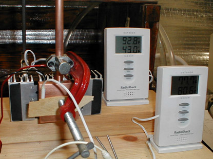
Through trial and error and refilling the
pipe with R134a a couple of times, I got the pipe to transfer heat from
one end to the other fairly quickly. It was time to get the pipe
out of the water and test it with a more powerful heat source.
 |
 |
 |
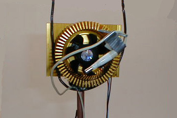
Using the heat sink tester I had built earlier, I began testing. Again, I had to adjust the amount of R134a a few times while watching the performance of the pipe. Too much R134a and it doesn't transfer heat at all. Too little and the pipe starts to transfer heat well and then all of the R134a seems to be turned to vapor (I'm guessing, as I can't "see" into the pipe) - stopping the heat transfer until some R134a condenses - then starts transferring heat again.
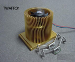
The table below shows Thermaltake's specs
for their new P4 heat sink I used for testing. As with all of the
Thermaltake sinks, it's neat looking and offers reasonable performance.
As I don't yet have a P4 to play with (and don't plan on having one for
a while) I thought I'd put it to work on this project.
 |
|
| Application: | TWAFR01
Intel Pentium 4 |
| Dimensions | 69dia x 55 mm tall |
| Clip type | TCS05(2x) |
| Fan size | 43x25mm 3-wire |
| Rated voltage (V) | 12 volt |
| Noise level (dBA) | 29.5 dBA |
| Air volume (CFM) | 23.1 CFM |
| Rated speed (RPM) | 5500 RPM +/- 10% |
| Heat sink material | Aluminum 6063 |
| Thermal resistance | THETA CA=0.48C/W |
After much fiddling, I received my best heat transfer results. The charts below show the performance with a 50 watt heat source. The first chart is with the heat pipe and the second is with the Thermaltake attached directly to the heat source without use of the heat pipe. These tests were not done under the best conditions and reflect a trend rather than exact results. I am working on building a new heat sink tester based on some ideas being exchanged by a group of people who would like to see more standardization of the heat sink testing done on computer cooling sites. There are some links at the bottom of the page if you're interested seeing some of the ideas involved.
In the below charts, compare the lines
for Hot Plate and Pipe
(Cold) on the top chart with the Hot Plate
and P4 Sink on the bottom. The closer
I can get the Pipe (Hot) to the Pipe
(Cold) on the top chart, the better
the heat pipe is working.
 |
 |
As you can see, the pipe has a long way to go to get close to the performance of the sink alone. While the results were not anywhere as good as I had hoped for, they were encouraging enough that I have begun working on an "improved" version. Remember that the heat pipe just "moves" the heat to another location and that the results of using a separate heat pipe with a heat sink attached will never be as efficient as using the sink alone. However, the use of a heat pipe will allow me to move the processor's heat to the top of the computer case, where I could use a heat sink triple the size of one that could fit inside the case. It isn't too much of a stretch to think that a very large sink with no fan could be used. Totally quiet cooling! Now, that would be nice.
OK, so what have I learned in my first attempt at a heat pipe? First, I've learned that I need to come up with a better pipe! I think I need more volume in the hot end. I am pretty sure that I am "boiling off" the liquid R134a before the vaporized gas can return to a liquid state so it can start the cycle over again.
I also need to come up with a method for measuring the volume of R134a in the pipe. Weighing the assembly (uncharged - then charged) with an ounce scale is not accurate enough. With the small volume of the pipe, my ounce scale barely registers a difference between empty and full. Perhaps a better scale would help ;-). Guessing at the amount of R134a I have in the pipe isn't a very good method.
For the second attempt, I am going to build a heat sink. I will use the same size hot side with 2 pipes going up to an array of stacked copper fins. The hot end base will be hollowed out to allow for more R134a. I will use a "screw in" service valve for the hot end and a couple of "solder on" valves to fit at the end of each tube. This will allow me to fill from the very bottom and vent from the highest point.
While I have done a fair amount of reading
on heat pipes, I am very much the novice in this technology. Suggestions,
as usual, are welcome.
Heat sink testing links
http://www.overclockers.com/tips240/
http://www.burning-issues.co.uk/how_to/TakingaTemp/takingatemp01b.htm
http://www.burning-issues.co.uk/hardware/hotair/hotair.htm
http://www.burning-issues.co.uk/hardware/calibrating/calibrating.htm
http://www.coolingzone.com/Guest/News/NL_DEC_2000/Tony/TK_Dec_2000.html
http://www.anandtech.com/showdoc.html?i=1136
|
|
|
|
© fager 12-16-00