
|

The primary plus in using water rather than air to transfer heat from the processor is water's greater thermal conductivity. Thermal conductivity is the measurement of the speed at which heat travels through a material through conduction. In the US, it is commonly expressed in terms of the number of BTUs of heat which will travel through one sq. foot of material which is one inch thick when there is one degree F temperature difference across the material (ie. Delta T). This expression is often stated as btu/in/hr/sq.ft/°F. In SI units, (SI = Système Internationale d'unités) this is expressed as W/m K, (watt per meter degree kelvin) which is the energy per second conducted through the material per square meter, when a temperature gradient of 1K/m is applied to the material.
So what's the difference in thermal conductivity
between air and water? About 30 times as great for water than for
air. (.02 W/m K for air and .6 for water.) The following chart lists
some common elements and compounds and their thermal conductivity.
change with the purity of the material. |
Over the past year or so, I have been toying with a bunch of ideas for water coolers. With a background in automobiles, I am pretty familiar with the concepts involved in a cooling system. I decided that I would start by building a small automotive type system with a water cooled version of an air cooled heat sink. This meant that the system would be self-contained - no hoses going to the kitchen sink and no open containers. The parts of the system are standard on any fluid cooled setup:
The water jacket to remove the heat. (The
heat sink.)
A radiator and fan to dissipate the heat
into the air.
And a pump to circulate the coolant.
I also wanted an easy way to change the
coolant and remove trapped air from the system.
The Sink
Since I had just finished testing the
aluminum and copper sink, I was still happy with the way the two metals
working together were able to remove heat from the processor. I decided
to build a scaled-down version of that sink to use as the "heart" of the
cooling system. The first sink would be a single TEC. This
choice was an easy one as I only had enough copper left for a single TEC
sized sink. I had learned a little about boring multiple holes in
copper from the last project. This is not quite as easy as it would
appear to get the holes to a line up - even with the use of a cross slide
vise - also known as an X Y table and vise. The small bits I used
for the pilot holes tend to "walk" a little - even when the copper is center-punched
first.
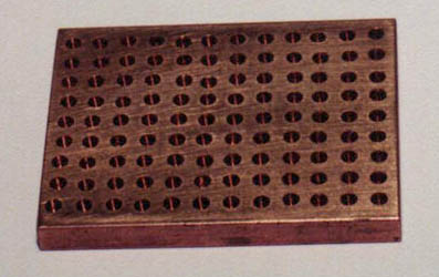
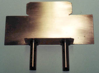
The holes are fairly straight, but still not perfect. The size of the base is 2" X 2.5" X 1/4". |
As with the last two-metal sink, the trick
for getting the pins in nice and tight is to bore the holes a bit undersized,
then heat the copper and freeze the aluminum. This gives you a couple
of minutes to insert as many pins as possible, then repeat the process.
I was glad that I only had 108 pins to insert this time.
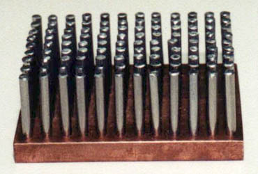
before being inserted into the base. |
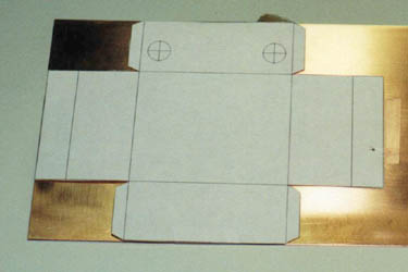
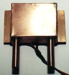
With the pins inserted, it was time to
turn my attention to constructing the water jacket. I wanted to be
able to solder the jacket to the base, so that meant using copper sheet
for the jacket. I made a couple "mock-ups" in cardboard before I
settled on a shape that I thought would work. I laid it out in AutoCad,
and cut a template.
|
Once the pattern was cut, I drilled a couple
3/8" holes, put a flange on the copper tubing, added some copper washers
and soldered in the tubes. I used a propane torch along with solid
core plumbers solder and flux. Soldering the tubes was easy as the
thickness of the tubes and sheet copper were about the same. I then
bent to copper sheet to give me the box shape.
|
The next step was probably the most difficult
of the project. I needed to solder 0.032" copper sheet to the 1/4"
copper base. I have done enough soldering and welding to know that
trying to get the two pieces of metal to about the same temperature is
the trick to getting a good joint. This heat sink was going to be
holding water with lots of electronics around it that would not take to
kindly to getting wet. I practiced a couple times on some scrap pieces
I had, before attempting to solder the joint. The 1/4" stock needed
to be heated without passing the torch on to the sheet copper. Since
copper is such a good conductor, the heat spread out to the sheet copper
with no problem. I liberally coated both sides with flux and soldered
away. Piece of cake - or to rephrase that, I got lucky. I finished
by soldering down the tabs on each end.
cleaner with a sheet metal brake, but not bad for a pair of pliers. |
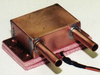
plate, the water box is ready to be installed on the insulated celeron. |
With the water box attached to the heat
sink, I added one 40mm TEC, some insulation, and the same cold plate I
had used in the air cooled version of the sink. During the initial
tests on the work bench, it was evident that I would need much more insulation
than the two small pieces I started with. I cut some styrofoam
to the same size as the Celeron and put that in place of the two small
pieces. This seemed to do the trick and focused the removal of heat
to the Celeron's slug rather than the air around the heat sink. Because
this was only a single peltier directly in line with the cold plate and
the processor's slug, it was very easy to insulate.
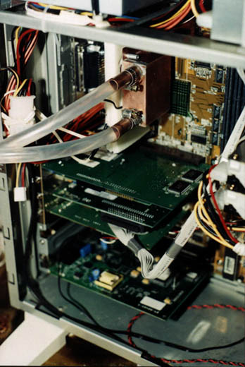
to a much larger piece during tests on the bench. Condensation was not a problem with this sink. (Yes, that's a bundled SCSI cable!) |