
|
 |
After the disappointment with the outcome of WC7, the journey to 1080 MHz with a 533 Celeron2 was a nice change of pace. As usual, there were some bumps in the road that had to be overcome, but hey, that's part of the fun of overclocking. Rather than feature the water cooler - as it is just WC4 with a different peltier - I will focus on the different things that had to come together to get this processor up to speed.
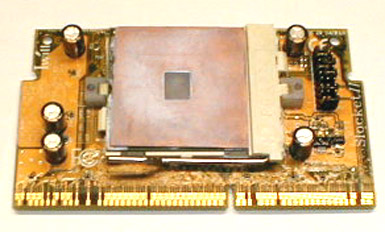
The Board - Asus P3-BF
When I purchased my last motherboard,
an Asus P3-BF, I did so because I thought I had killed my previous board,
an Abit BX6r2. It turned out that the BIOS in the Abit just needed
to be re-flashed, and all was well, but I have
been using the P3-BF as my main computer's board ever since. I had
been using Abit boards exclusively up to that point. The switch to
the Asus was, well, different. It's not that the Asus hasn't been
a good solid board, but I was used to the way the Abits reacted to overclocking
situations. One thing in particular that I couldn't get used to was
the way the P3-BF reacts after setting the parameters in the BIOS a bit
too aggressively. The way it handles a missed bootup is to give an
error, or hang and then when you shut down the power and reboot, it brings
you directly back to the BIOS setup screen. Abit, on the other hand,
will give an error or freeze and then on a cold re-boot, try to boot up
using the settings last saved in the BIOS.
Now, I think I understand Asus's reasoning. If you couldn't get through the boot process, you probably chose a setting that you shouldn't have and so it's back to the BIOS setup screen to set it correctly. However, anyone who has played with computers for a while has probably found that a power-off re-boot often works better than a power-on reset.
During the months that I used the Asus, I often felt that if I set a speed in the BIOS that was on the "ragged edge" of stability, that the ability to try a cold start up at that setting might have given me some successes where I was receiving failures. As it turns out, my feelings were correct.
One other strangeness of the Asus board was +12 volt reading from the BIOS, or other voltage monitoring software. While every other board I have hooked up the the Powerman 300 watt supply in My In-Win Q500 case read around 11.98 to 12.02 for the 12 volt reading, the Asus read 11.58. The voltages for 5 volt and 3.5 volt were a bit low as well.
In the Asus's favor, the board has been as stable as any board I have owned.
The Abit BF6
As I stated in a previous news update,
I was in the market for a new board and the current new boards being offered
didn't do much for me. I have been a fan of Abit's boards ever since
they came out with the first Soft Menu. After weighing the pros and
cons of all of the available boards, Soft Menu 3 made my decision an easy
one. An Abit BF6. All of the good without the somewhat problem
prone High Point ATA66 controller of the BE6-2. Being able to increase
the Front Side Bus speed in increments of 1 MHz at a time is a overclocker's
best tool to squeeze every MHz out of the processor.
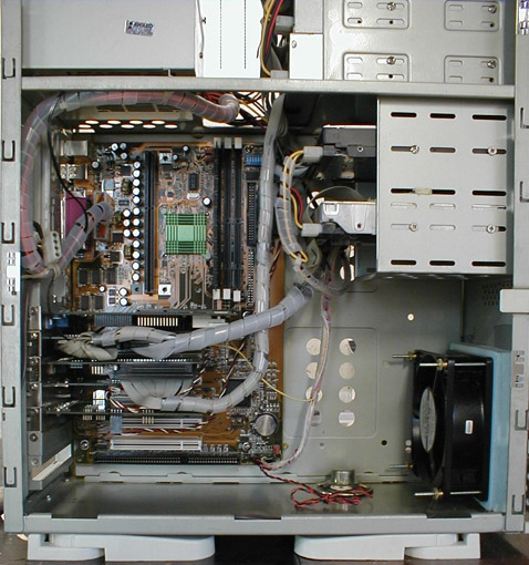
The installation into the In-Win case was
uneventful, aided by the now familiar, exemplary manuals that Abit provides.
One minor setback in getting the system up and running was loosing the
keyboard function immediately after exiting the BIOS setup screen.
I have Tweak-UI installed and set to bring up the boot options screen so
that I may choose to boot to DOS or as in this case, a safe boot.
I was unable to switch from a "regular" to a "safe" bootup. The loss of
the keyboard ended up being the plug for the hard disk LED being plugged
in backwards and causing a grounding issue. I've miss plugged these
leads before with the only outcome being that the LED didn't function.
Loosing the keyboard because of this was a new one on me. Fortunately,
a quick search on Deja
for "keyboard error abit" brought up a post of someone who had experienced
the same problem and I was back on track in no time. Aren't the newsgroup
archives great?!
 |
A quick note on changing motherboards without doing a complete reinstallation of Windows. I used to be of the opinion that installing a new board worked best with a new installation of windows. I no longer feel this way. My procedure now is to copy the Windows CAB files and all of the driver files to a folder before changing the motherboard. On first bootup, I boot up in safe mode. I then go to the device manager and remove EVERYTHING. There are always a few things that don't appear to come out - the primary and secondary IDE controllers, for example, but they are actually removed when you remove the Bus Master IDE controller. Once everything has been removed, shut down and restart. When asked for the Windows CD or drivers, point it to the correct folder. No fighting the red X's and yellow !'s as you do if you don't remove the devices and no 3 hour reinstallation of every program you own (even if you, like me, keep all of your programs on a separate partition). The reason for the CAB files and drivers on the hard drive is that, in my case, the CD is SCSI and Windows likes to load the video drivers before the SCSI card. No CD, no drivers, no video card gets installed - unless the drivers and CABs are on the hard disk. I have used this method a number of times now with complete success, but I still make an "up to the minute" backup of the entire hard drive to CDs before the motherboard swap. No sense in tempting fate.
Shims
The small size of the PIII and CII processor
is both a blessing and a curse. On the one hand, not having the metal
case (slug) that has been present on previous versions of Intel's processors
means that you can get your heat sink (or, in my case, cold plate) directly
on the wafer. As long as you get good contact, you can cool the heck
out of the chip. On the other hand, the chip is small and it doesn't
take much misalignment to have the heat sink not contact the entire chip.
There are a couple of ways to get around
this problem. One is to use small "feet" (stand-offs) on the bottom
of the heat sink to keep the sink from tipping from side to side.
 |
Another way to keep the sink from misalignment
is to use a shim. I have seen and made shims of aluminum and copper.
I am considering making one of silver. I have also seen and made
shims in a couple of different styles. Whatever the style or material,
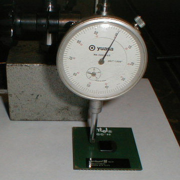
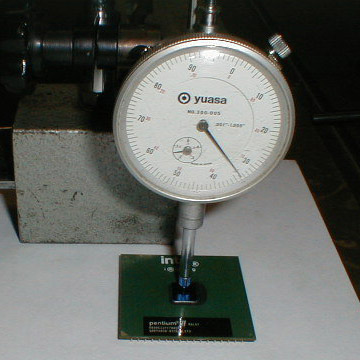
the crucial design consideration is the thickness of the shim. Intel
states that the height of the top of the substrate to the top of the wafer
is from .031" to .035" (1.0 to 1.2 mm). In the 3 chips - 2 PIII and
1 CII - I have measured, they come to about .033" plus or minus a hair.
 |
 |
33 thousandths. OK, so if we allow a thousandth for heat sink compound, and use standard 24 ounce (21 gauge) copper sheet, which is supposed to measure 32 thousandths, we're in there at the perfect height, right? Wrong. The heat sink compound doesn't take up one thousandth and all of the copper and aluminum sheet I found was a bit undersized. As if that weren't enough of a challenge, there's another. The PIII label sticks up about a thousandth and the white embossed lettering that says Intel sticks up about the same amount. The glue on the right side of the wafer also sticks up above the substrate. Making a shim that fit exactly was going to take some work.
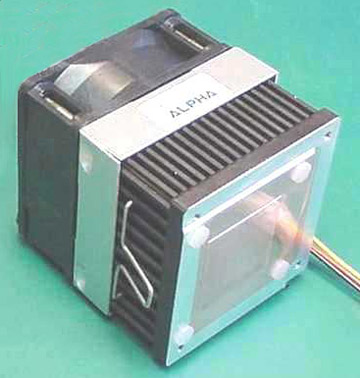
I'm still playing with shims, but have made a couple (out of numerous tries) that get good contact and keep the sink completely level with the processor. If you're wondering why I decided to go the shim route rather than stand-offs, it's because of the peltier. I wanted to get as much heat removal as was possible. Even though the substrate is not a particularly good thermal conductor, some more heat removal through the substrate is better than nothing. I reasoned that the more of the entire processor package I could chill with the peltier, the colder I could run the processor. As it turned out, this setup worked better than no shim by about 8°F using the stock heat sink and fan when the system was pushed to its limits. I have no idea how much of an increase it made with the water cooler and peltier as I never ran it without a shim.
One word of warning that you may or may not want to heed concerning how tight to mount the sink to the chip. Intel states in the Flip Chip Data Sheet that you need to be wary of the amount of pressure applied to the silicon die surface and edges. The specs are as follows: a maximum of 25 foot-pounds static and 200 foot-pounds dynamic for the die surface and 12 foot-pounds static and 100 foot-pounds dynamic for the silicone die edges. This is taken from table 28 in the PDF (page 45 in my copy).
One last note on shims or stand-offs.
With a standard heat sink, where you can see if the alignment is correct
by holding the sink and processor up to a light and looking at the fit,
you can then adjust for a poor fit by moving the sink. It is possible
to use no shims or stand-offs and still get good contact if you are careful.
With the water coolers and TECs, insulation is a must. This means
that once you drop the cooler on the processor, the alignment is hidden
by the insulation. If it's not right, you won't know until you fire
it up and check the temperatures. Using stand-offs or shims helps
make the alignment automatic. On WC7,
when I was having "issues" with the Iwill slotket, I had to tear the cooler
down many times to double check the alignment. This got to be a chore.
 |
|
|
|