
|
After doing some research to see what others had done in designing testers, I decided that I too would use a peltier. In thinking about using a bare TEC, I realized that there would be no way to measure a sink's true performance if I just measured the temperature of the heat sink. I would need to simulate a processor in between the TEC and the heat sink and measure the temperature of that. This would allow me to see how well the heat sink cooled a known heat source, rather than just measure the temperature of the different sinks.
I also decided on using a "cold sink" to
try to stabilize the amount of heat the TEC produced. I suppose that
I could have just used a block of aluminum for this, but I had an old heat
sink that was already drilled for both the slot 1 Celeron and PII, which
would save some time. I just needed to add some mounts for the socket
7 / 370 sinks and (later) for the PIII and Athlon. The tester also
had to be able to support the processor as it would attach to a motherboard.
This is not so important for air-cooled sinks, but would be important
when I started testing fluid cooled devices.
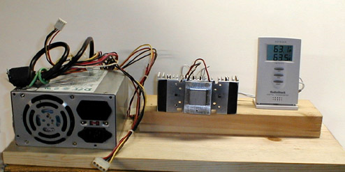 |
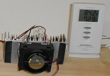
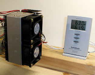
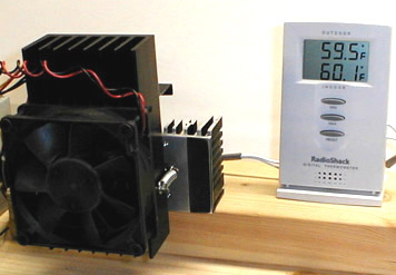
I started by modifying
a Radio Shack Thermometer to use to read the results.
I added an 250 watt AT power supply to provide the power for the peltier
and any fans the heat sinks might use. I mounted both of these permanently
to some scrap lumber.
 |
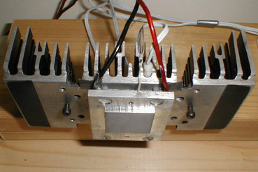
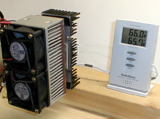
I was looking for a peltier that would simulate a "standard" processor. From my box of peltiers, I chose a 40 X 40 mm TEC that when tested with a voltage / amperage meter, draws 3.2 amps at 12 volts (38.4 watts). For the heat source unit, I made my usual sandwich of a sink, peltier and plate. The difference here was that the roles of the components were reversed. The cold plate became the hot plate and the heat sink became the cold sink. I machined the hot plate to have a 1" square contact area to simulate the slot 1 and PPGA Celerons. The plate was attached to the sink with nylon screws to minimize heat transfer between the two. The plate is removable, so when I start testing PIII and Athlon heat sinks, I'll be able to swap it out for a plate with the correct size processor contact area. I drilled a small hole in the edge of the plate and sunk the small thermistor from the RS thermometer in the hole. It was surrounded in thermal paste to get the best possible contact with the plate and still be removable. The second, larger, thermistor probe was tightly wedged in between the fins of the cold sink.
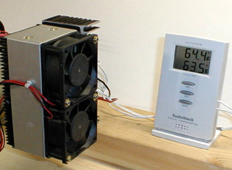
I made some small mounts up to allow the assembly to be mounted in either the horizontally or vertically. This was done with just a couple of screws and washers. The assembly does not have to support a lot of weight, so the screws just slip between the fins of the sink.
Before I started using the tester for the
purpose of designing a new heat sink, I wanted to test it on some known
sinks to see if the results matched my previous findings. This got
interesting very quickly and I've decided that I will eventually re-test
all of the sinks I have tested in the past. (Those that I still have,
anyway.) I'm somewhat surprised by the results I received in the
first batch of sinks I tested.
 |
 |
As with most things, it's best to start at the beginning. For the tester, this meant testing it bare. Having never run a peltier without a heat sink attached to the hot side, I didn't have much of an idea of what to expect. I knew it would get hot, but I wasn't prepared for how hot. In a half minute, I had exceeded the 158°F limit of the RS thermometer and had to switch to my Omega thermometer. In less than two minutes, I had seen all that I needed. 243°F and climbing. As I had no desire to kill the TEC, I stopped the test there. Since this is supposed to be a heat source, I guess it should get hot.
If you have done any reading on TECs, you
know that a TEC on top of a processor means that the heat sink has to cool
them both. If the heat sink can not handle the heat load produced
by both, the processor will end up running hotter than it would without
the TEC. While the above example is extreme, it does illustrate that
without a way to get rid of the heat, a TEC is useless. Note that
before two minutes have elapsed, the cold sink is hotter than with no TEC
running.
 |
 |
Since my upcoming project is based on a
socket 7 / 370 style chip, I decided to, once again, see how the standard
boxed Celeron 366 heat sink and fan worked. My results were about
what I thought they should be, with the high temperature matching up pretty
close to the temperatures I had observer while testing
this sink on a C366 at 366 MHz. I though the sink was a bit anemic
then, and my opinion hasn't changed. Notice that at about the 170
second mark, the temperature of the cold sink begins to rise. This
indicates that the heat sink is not able get rid of the heat as fast as
it is being produced by the TEC. Similar things happen when you try
to use a TEC with too small of a heat sink on your processor.
 |
 |
The test of the Alpha P125 shows that it
easily handles the heat being generated. Once it reached its working
temperature, the cold sink continues to drop in temperature. I had
done some testing of the P125 in both "blowing" and "sucking" configurations
before, and decided to try it once again. In the past, I never really
saw that much of a difference in the two configurations, but "sucking"
air from the sink seemed to work a little better on the setups I tried.
This testing seemed to reinforce my earlier thoughts, but there is not
all that much difference between sucking and blowing. => No snide
remarks from the peanut gallery, please. ;-)
 |
 |
Here again we see good results from the
P125. This time in suck mode. Again, the cold sink continues to get
colder after the sink gets up to operating temperature. I find it
interesting that the temperature of the hot plate cools a couple of degrees
after the sink has been running for a while. I initially thought
that the TEC might have been drawing less power at that time, but with
a V / A meter attached, I found that this wasn't the case. While
I did observe this phenomena in the A&C prototype to a lesser degree,
I didn't see it in the "big sink." Strange.
 |
 |
The A&C
prototype was my attempt at a high performance, air-cooled heat sink.
At the time I first tested it, the result were encouraging, but the amount
of labor involved to build it was staggering. Using the same fan
shroud as with the P125 with a pair of 60 mm, 12 volt, 3800 RPM, 25 CFM,
Orion fans (Allied #592-0690) the high temperature of the simulated processor
was 115°F. That was 11 degrees cooler that the best from the
P125. Again, the heat sink temperature dropped slightly after being
at operating temperature for a few minutes. The temp drop was minimal
(0.6°F), but there.
 |
 |
This "Big" Sink's performance was a surprise as it has been a long time since I have even thought about it. I pulled it from my K6-233 running at 250 on an 83 MHz bus. This is the chip that I will be building the new cooler for, since it is now working in my Linux server. The big 4" fan just makes too much noise to leave it running 24 / 7. Because of the large mass of this sink, it ended up with the best results so far, topping out at 109°F on the hot plate. Even with the big, noisy fan, it could use a bit more air flow as shown by the gradual temperature increase. Even so, after an hour of testing, it was still the best performing sink of the bunch.
If it wasn't for the fact that I want to build a self-contained water cooler for this box, a better fan would probably keep the noise level to an acceptable level and offer all the cooling I need. But since I want a small, self-contained water cooler, I won't leave "well enough" alone. Such is the life of a tinkerer!
Now that the test equipment is done, I get to start building the cooler. I will update this page with other heat sink tests as I get the time. I'm really curious to see how the water coolers - 1 through 4 - fare on this tester. As hard as I have tried in the past to keep my tests as constant as possible, a dedicated tester removes a few more variables from my testing. The only one I can't do a lot about now is ambient temperature. Now, if I could just talk my wife into letting me turn the basement into a temperature controlled environment....