
|

With the addition of a small dedicated server to my home LAN to handle the tasks that were beginning to weigh down my main box, I started thinking about making this box as quiet as I could. As this box runs the infamously hot AMD K6-233, the cooling was going to have to be better than average.
My initial thoughts on this were to run a water cooler with no pump and no fans. Just circulate the water by convection. I tried this by making a closed loop system with the water block at the bottom of the loop and the radiator placed above it. As the water in the block heated up, the heated water would rise to the radiator, cool, and travel down the second hose back to the block. Testing this design on the heat sink tester, I found that if I allowed a few minutes for the temperature difference between the block and the radiator to get to more than about 25°F, the water would begin to circulate. Slowly, but it did circulate. After weeks of testing different configurations, I came to the conclusion that this set up would not produce the results I was after. Yes, it did work, but convection alone wasn't producing enough of a flow to deal the heat from the processor. It did keep the K6 from going critical, but could not keep the processor under 100°F in a 70°F room. To get to those temps, I was going to have to use a pump. So much for absolute quiet. (Even if I could have figured a way to run the power supply without a fan and muffle the hard drives.)
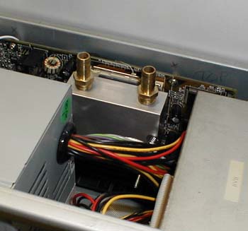
Another consideration for this box was to make the system small enough to fit in or on the case. I didn't want a separate box for the pump and radiator. With this in mind, I set to work on the first prototype.
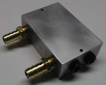
Water Block
The design of my water blocks continues
get simpler as time goes on. The simplicity has certainly saved me
some time in the workshop. This water block is about 2 15/16" by
2" by 1" in size. Four 7/16" holes with 1/4" NPT threads cut for
the nipples and plugs, and two 1/8" holes for the hold down hardware.
It doesn't get much simpler than this - six holes, four of which are partially
threaded.
While this project is not using peltiers,
my testing on the bench shows that with a properly sized radiator, this
block will handle the 117 watts of heat that is typical of one of my dual
peltier set ups. [A 45 watt processor and two 30 mm peltiers running
at about 36 watts @ 12 volts each. The peltiers are rated at 52 watts
@ 14.4 volts The working wattage was estimated by: (actual voltage
/ rated voltage)² × rated watts = actual watts - and was
verified with an ammeter reading of 3 amps @12 volts for each peltier.]
Of course, the key words here are "properly sized radiator." Since
the radiator is what dissipates the heat, it is the part that most influences
the overall performance of the system.
|
|
Pump
Since I would not be using peltiers on
this project and the vertical distance the water needed to be pumped was
only about 17 inches, I could get away with a fairly small pump with a
lower flow rate than I had used before. I found a Little Giant
model 567005 pump at the local hardware center that looked like it would
do the job well. This pump is rated at a maximum of 95 gallons per
hour and is listed as having the ability to lift water a maximum of 4 feet.
This is still probably overkill for this project, but the next smaller
pump they had in stock was a bit on the anemic side.
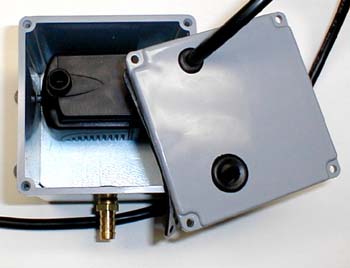
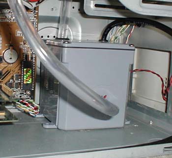
I really liked the idea of a closed container that was as near to leak proof as I could get for the purpose of bleeding air from the system. As I was now using a submersible pump, the container would now also have to house the pump, as well as bleed air from the system. As I had good luck with the last PVC electrical junction box I used, I stuck with what worked. I added a 1/2" of foam to the bottom of the container and attached the pump to the foam with some silicone sealer. I hoped that the insulation would help deaden the noise from the pump. It worked.
After finding some rubber grommets that
fit snugly on the 1/4" electrical cord and 1/2" OD plastic tubing, I drilled
the top of the container with holes that were slightly undersized for the
grommets. It was a bear to get the grommets into the undersized holes,
but I wanted to make sure that even if the case was knocked over, it wouldn't
leak. With a little lubrication on the cord and tubing, it was fairly
easy to thread the hose and cord through the grommets. One unfortunate
side to this particular pump is the fact that there is no easy way to disassemble
the pump to remove the cord. This meant cutting the cord to thread
it through the grommet. This was not too bad as I wanted to shorten
the power cord, but I would have preferred to not have to use an "add-on"
plug.
|
|
|
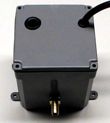
As I said before, one advantage of the
container is the fact that it acts as a self bleeder. As you fill
the system with water / antifreeze, some air remains trapped in the system.
Once the pump is turned on for the first time, the air is pumped through
the system and gets trapped in the top of the container. Since both
the inlet nipple and pump inlet are below the water-line, no air is pumped
out of the container. This saves lots of headaches in trying to bleed
air from the system. It is a good idea to assemble the entire unit
out of the case, fill it, and figure out exactly how much water it will
take to fill the system leaving a small air pocket at the top of the container.
This will save some guess-work when adding the coolant to the finished
system.
|
|
|
|