
|
In the last installment, we left off with
a seven fin sink that cooled the test heat source down a bit, but still
suffered from lack of enough performance to make it a viable alternative
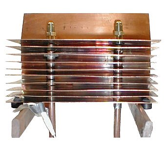
for a fan cooled heat sink. The plan was to add the remaining three
copper sheets and test again. This was exactly what was done.
Unfortunately there was a lack of foresight on my part. In drilling
the holes for the previous seven fins, I had clamped some wood to my drill
press table to form a jig. This allowed me to drill each hole in
exactly the same location for each of the first 7 fins. While I still
had the jig set up, I neglected to drill the remaining three. Of
course, just after I had unclamped the jig, I realized I still had three
to go. Bummer. I ended up drilling a couple (is six still considered
a couple?) of cardboard sheets until I got the alignment of the holes back
to where they would fit. Even then, the fit wasn't exact and I had
to do a little filing to get the fins to slide down the tubes. The
copper washers served double duty and aside from their intended purpose
of giving each fin better contact with the tube, they hid my lack of perfectly
round holes. As usual, I live and learn.
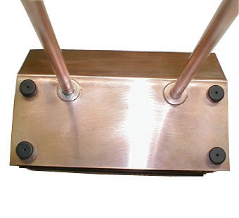 |
The concept I had for this sink had it
sitting atop the computer case. To be able to fully utilize the bottom
fin, it would have sit up from the top of the case enough to allow for
air to get to the under side of the fin. I was thinking about using
rubber "feet" of some kind. I then remembered that a blender I had
purchased many years before had come with extra rubber feet. Being
the wise pack rat that I am, I had stashed them away as "future useables."
It didn't even take long to find them - filed away next to the spare spark
plug from a previous lawn mower. Yep, I have lots of valuable stuff!
 |
 |
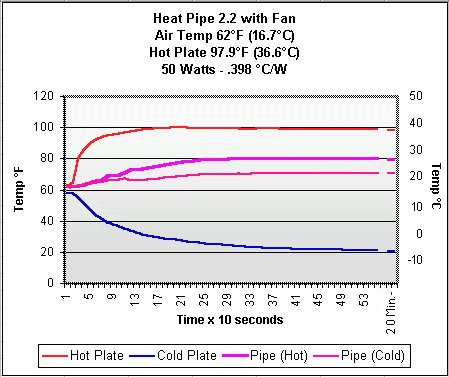
With the three additional fins in place, it was time to fill the heat pipe with R134a and do some testing. My method for filling the heat pipe (found here) has been simplified a bit. I no longer freeze the pipe and R134a. I filled the pipe at my basement room temperature which stays at about 62°F (16.7°C) during this time of year. I then attached the heat pipe to the sink tester and crank up the heat source. I vented a little R134a over the course of a half hour or so while watching the difference in temperature between the base end of the pipe and the fin end. When they equalized, the pipe has the correct amount of R134a (or as close as I can get it).
As for testing the sink, I have to preface the tests with the admission that my heat sink tester sucks. While it does give me useful information in terms of comparison, the figures you'll read for °C/W are not accurate. Using a peltier as a heat source - especially the way I have it set up with a "cold sink," offers too many variables to correctly figure the heat (in watts) produced. One of the troubles with this design is that the amperage draw of the peltier changes with its temperature. Another problem is that the cold sink temperature goes sub-freezing and tries to draw heat from the room. This causes more heat to be passed to the hot side of the TEC than the amperage would indicate. Of the two problems I have mentioned, the lessening amperage draw of the TEC is the worst offender. As my ammeter is not inductive and the shunt gets *really* hot after only a few minutes, it is difficult to plot the amperage draw, but I have measured up to a 50% reduction in amperage at the end of a half hour's test.
I want to add that while the figures I come up with for heat dissipation are not something that could be reproduced on another tester, they do give me good comparative information. I am able to reproduce the same results time after time and this does help with the evaluation of the projects I work on. I just can't compare the results with anybody else's tests. As I mentioned in the Heat Pipe1 article, I am working on a new tester with a resistance heater with a few other people. Now that the heat pipe project is at a point where thoughts of it don't fill my head all of the time, I hope to turn my attention to building a new tester.
The figures for °C/W on the "on box" tests are probably much closer to the truth.
Bench tests
I ran three tests, three times each.
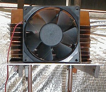
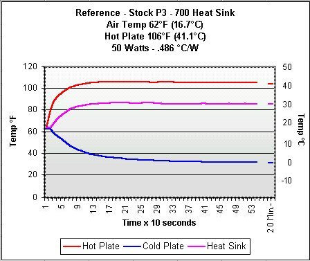
Heat pipe sink alone, heat pipe sink with a 3½" fan in front of
it and a reference test using a stock Pentium III heat sink and fan.
Here are the results.
 |
 |
 |
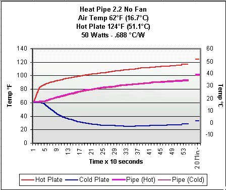
As you can see in the charts, the performance has improved with the addition of the three additional fins. In the first chart, the heat source high temperature has dropped 5 °F (2.8 °C) from the 129 °F (53.9 °C). While this is not a fantastic amount, if my processor put out as much heat as the test heat source (it doesn't), I would still be well under the maximum high temp for the PIII processor I intend to cool with the sink.
With the addition of a 3½" case fan blowing on the sink (low cfm and quiet old fan out of a 386 computer) the performance beats the performance of the stock PIII heat sink and fan by a substantial 8 °F (4.5 °C). I would imagine a little ducting would increase the "with fan" performance even more.
Assembly
I started this project trying to get a
home made heat pipe to work. I figured if and when this happened,
I would deal with how to attach it to one of my boxes. The time to
do the attaching was now at hand.
The first problem I encountered was that all my cases had the power supply directly above the space where the processor sits on the motherboard. Since the heat pipe's condensed liquid returns to the block by gravity, the path from the radiator (sink) on top of the case to the block needs to run "down hill" the whole way. In some bench testing, I found that the performance of the heat pipe degraded as the slope of the tube became more horizontal. Forty-five degrees was about the maximum I could go without too much of a performance penalty. Unfortunately, due to the fittings on the block and the lack of space between the block and the power supply, the slope would have to be about 30° with the P/S in its stock location. This wouldn't work.
Another concern was that mounting the sink on the top of the case would require cutting a couple of holes in the top of the case. Since I wasn't sure that this version of the heat pipe would be the one I would end up using permanently, I was not anxious to cut holes in my new InWin Q500N's case.
I decided to attach the heat pipe sink in a temporary setup first.
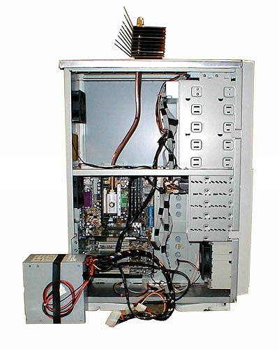
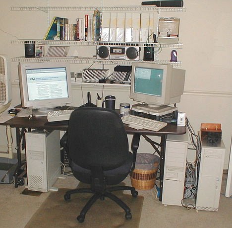
I found that there would be enough room for the tube to be at a workable angle if I moved the power supply up a few inches. In the picture below, you can see the hole on the left side of the top of the case (below the fan) where the power supply resides normally. If I moved the power supply up to where the case fan now sits, the tube angle would be OK. I measured to ensure the P/S would clear the tubes and bent them to fit.
Since I was unwilling to cut holes in the top of the InWin case, I made a new case top from sheet aluminum. I won't go into the design and execution of this, but if you will imagine making a large shoe box lid, you will get the idea of how it was made. Twenty minutes with a pair of tin snips and blocks of wood to form the bends and I had a workable top cover that fit pretty well. (No, I don't happen to have a metal brake (sheet metal bender) as a part of my workshop - but I'd like one!)
As for moving the power supply, not now.
I decided to just leave it outside the case for the "on box" testing.
If after a month or so, I decide I like this setup, I'll mount it permanently
by cutting the necessary hole where the top case fan now resides.
With the tubes bent as they are, it will fit with no problems. (Yes, I
did check to make sure that the wires were long enough to reach their respective
locations, thank you. ;-))
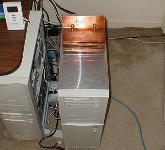
 |
There wasn't a whole lot of work involved
in getting the heat pipe sink in place once the new aluminum case top was
fabricated. The copper tubing is easy to bend and allows for pretty
easy adjusting to get the block flat against the processor. Having
the power supply outside the box with wires everywhere is, uh, typical
for me.
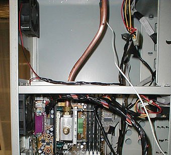 |
In the picture above, you can see the block
and hold-down clamp. (The piece of scrap metal with numbers on it.)
I used the same setup as I used in water cooler 4's hold-down,
but used a separate bar to hold the clamps. This works well and the
clamping pressure between the block and socket can be adjusted. The
block is held flat against the processor by the use of an aluminum shim
and the heat is spread by the use of an additional copper shim
that I made up for the NT Box. Holding the block flat is a major
concern as there is a lot of rigid plumbing attached to it and to have
less than full contact between the block and processor would spell disaster.
 |
The processor core high temperature results
when running the 3½" case fan in front of the sink were as good
as most high performance heat sinks. I am considering making a permanent
housing for a small thermostatically controlled fan (similar to this
one) that would kick in if I needed it. While the chances that
I would ever run the box at full tilt for 40 minutes are next to nil, I
like the idea of insurance.
 |
 |
 |
Conclusion
This has been a most interesting project.
Being able to make a working heat pipe was cool. Getting it to actually
cool a processor was an added plus. Now that I know that it is possible
to cool a CPU by a home built heat pipe contraption, I am thinking toward
the next step. Designing a case as a heat pipe sink. With some
thought, it should be possible to make a case where the case itself is
the heat sink. As it stands now, the computer case is nothing more
than a box that holds all of the components. Why not make it a working
part of the computer?
 |
|
|
|
|
© Fager 1-21-01