
|
![]()
After playing with
Heat Pipe 1 for a while, I came to the conclusion that I needed greater
fluid capacity in the base. I was fairly sure that the R134a was
being "boiled off" quicker than it was being condensed and returned to
the base. It was time to start work on heat pipe 2 and try to correct
this problem. I also wanted to try my hand at actually making a heat
pipe heat sink, rather than just a test pipe.
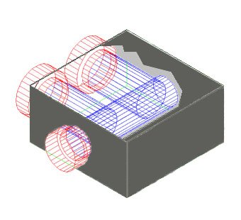
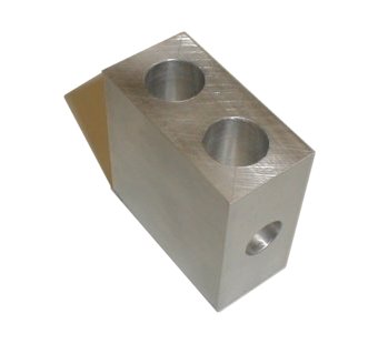
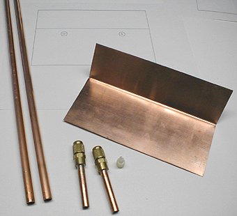
I happened to have
some 2 inch by 1 inch aluminum stock from a previous project and started
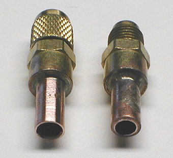
by cutting a 2 inch length. Holes were drilled for the two 3/8" NPT
and 1/4" NPT fittings. OK, I hear you, "Those holes are a lot larger
than 3/8 inch and 1/4 inch, what gives?" Good question. The
3/8 NPT and 1/4 NPT refers to pipe threads and are described by the inside
diameter of the pipe or fitting, not the external dimensions. The
actual drill size for the 3/8 NPT thread tap is 19/32" and the size for
the 1/4 NPT is 7/16". The service valve (below with cap) has 1/4"
NPT on one end and 5/16" flare on the other. The "1/4" end is larger
than the "5/16" end. It can get confusing if you don't keep the "thread
type" in mind. Excuse me for not converting to metric, but I don't
have a clue as to how metric pipe fittings are measured. One would
hope that it is a more harmonious system.
 |
 |
 |
 |
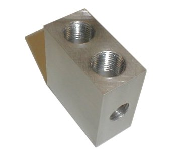
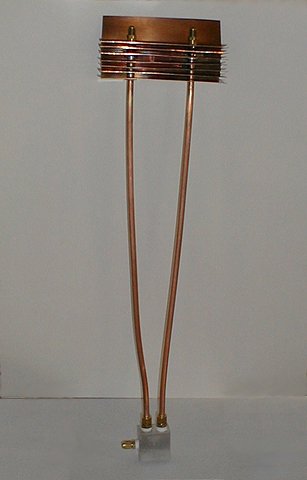
Once the base was assembled, I used water from a syringe to measure the fluid capacity of the block. It works out to about .46 US fluid ounces (13.5 ml) to the top of the inner shoulder of the top fittings. This is about 6 times as much capacity as the previous heat pipe.
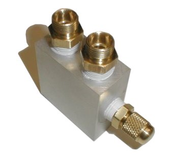
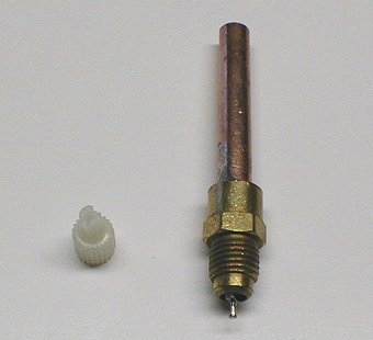
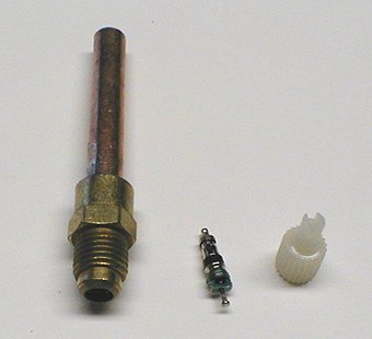
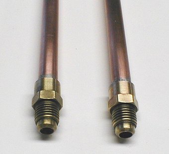
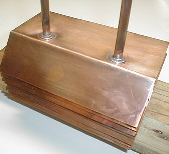
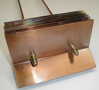
The next step was to work on the "heat sink" end of the assembly. This was composed of the two 3/8" (9.5 mm) (outside diameter) copper pipes soldered to seven 5" x 7" x .022" (127 x 178 x .56 mm) copper plates. The tubes are standard plumbing fare, picked up at the local home center. The service valves are a specialty item. They come with a length of 1/4" outside diameter tubing pre soldered to the fitting. Since the 3/8" outside diameter tubes have an inside diameter of 1/4", they fit together perfectly. I picked these up from a local HVAC (heating, ventilation, air conditioning) supplier named Aireco. They are high quality parts and have removable schrader valves which need to be removed when soldering.
As for the plates, I have to thank the
fact that I am known to watch the home improvement shows on TV. Dismayed
that the price of copper sheet is so expensive when purchased in small
quantities - try up to US$ 12.75 for a 12' (30 cm) square at one of the
popular online suppliers - I was looking for another source. I happened
to see a show where they were doing roofing repairs and used copper flashing
to protect the valley where two roof surfaces met. The copper looked
perfect for the project. A trip to the local roofing supplier found
me with 10 sheets at US$ 1.75 per sheet. Much more reasonably priced.
One "drawback" that I decided to ignore was that the sheet comes present
at a 90° angle leaving three inches on one side of the bend and two
on the other. No big deal, it might actually help get the heat away
from the fins. As the flashing is not used for "show," my pieces
were not the prettiest pieces of copper I have seen, but they straighten
and clean up easily if you don't mind some scrubbing.
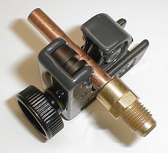
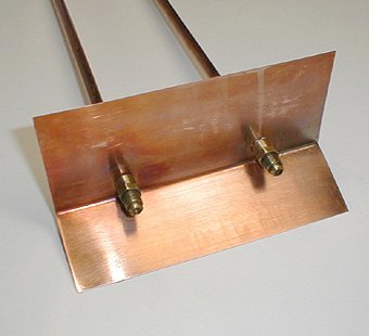
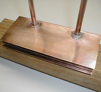
The assembly of the heat pipe sink was pretty straight forward as the following
pictures show:
 |
 |
 |
 |
 |
 |
 |
 |
 |
 |
 |
 |
As I did with heat pipe 1, I weighed the unit once it was complete. This beast weighs in at a hefty 2 pounds 13 ounces (1.28 kg). After filling the the pipe full of R134a, (see heat pipe 1 for the procedure) it weighed 3 pounds (136 kg). Three ounces (89 ml) of R134a. Since the block itself only holds .46 oz., I was full to the top of the tubes. As with heat pipe 1, I started testing in the basin with hot water and venting R134a until the pipe started to perform well. Once I had the best possible performance, I re-weighed the pipe to find that a little over an once of R134a seemed to be the magic number for this project.
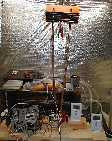
On the tester, I set up with one sensor on the aluminum base's back side and one sensor taped just below the bottom fin on the pipe. While the overall performance of the sink as a "no fan" sink is not yet up to par, I was amazed to watch the hot and cold end temperatures. The cold side lagged behind the hot side by a few seconds, but the temperatures between hot and cold never varied more than about 3°F (1.7°C). This was hoped for but unexpected after heat pipe 1's 20 + degree difference. Be assured that I had a smile on my face for this test.
Since the temperature kept rising, I knew
that the 7 fins were not doing their job well enough to handle the 50+
watts of heat that the peltier produces. I decided to hold a 3 inch
fan in front of the fins to see how far the temperature would come down.
About 20°F (11°C) in 5 minutes with the hot side still trying to
equalize with the cold side. I'll have to rig a holder to do a complete
test using the fan, as the thought of holding the fan in place for 20 minutes
doesn't thrill me.
 |
 |
 |
As I said, next I will add more fins and continue testing. I may also try using water under a partial vacuum as the working fluid, though I had originally planned to do this only if I couldn't get the hot and cold side temperatures close. We'll see how the performance is using a fan and then with more fins. Once the performance is good enough to handle the ~30 watts of an overclocked P3 - 900, I'll start converting the box to accept the heat pipe sink.
Lots to do, but it should be fun.
|
|
|
|
© fager 12-30-00