
|
 |
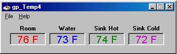
I have finally finished coding the gp_Temp4 software (more or less) as I originally envisioned it. If you're interested in building the thermometer, I suggest that you take a look at the previous gp_Temp article for some background and a little history of the project. I went into a bit more detail in the original article than I will do here.
gp_Temp4 will allow you to read four - 10 k to 200 k thermistors from the gameport connector of your computer or soundcard. The resolution is 1° on either Celsius or Fahrenheit scales. The accuracy is within a degree in the center of the range and within 2 to 3 at the extreme ends of the range, depending on thermistor type and resistance value. The range for different values of thermistors are as follows:
10 k ohm thermistors can register a range
of -40°C to 25°C (-41°F to 77°F).
50 k ohm thermistors can register a range
of -3°C to 65°C (26°F to 150°F).
100 k ohm thermistors can register a range
of 7°C to 77°C (46°F 171°F).
Hardware
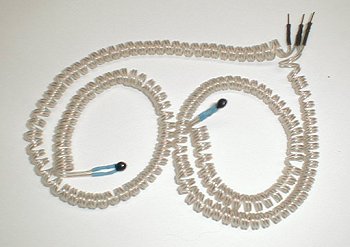
The setup of the hardware is identical
to the gp_Temp project with the exception that you will want to build two
thermistor pairs rather than just one. The setup of a thermistor pair
can be found here.
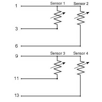
The connections for the thermistors are made as follows:
 |
 |
 |
 |
Software
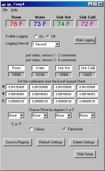
Hopefully I have simplified the setup
interface a bit. I have taken away the choice of multiple thermistors
on each port as I didn't really think it would be used by anyone but me.
I initially used it for checking thermistors of different values while writing and testing
the program.
 |
 |
To get gp_Temp4 going, you'll need the program:
gp_Temp4.zip
and the Excel spreadsheet for figuring
the coefficients:
steinhart.zip
A screenshot of the spreadsheet can be found here.
Here is the software portion of the readme from the program. It should give enough information to get the program up and running.
**********************************
Windows 98 SE Driver Setup
**********************************
WARNING: Do not use Windows Calibration utility!
1. Click "Start" | "Settings" | "Control Panel"
2. Double click "Gaming Options" (Joystick Icon)
3. Click "Add"
4. Choose "2-axis, 2-button joystick" | Click "OK"
5. Click the "Controller IDs" tab
6. Make sure that the "Port Driver" box reads "Standard Gameport"
7. Make sure that the "Poll with interrupts enabled" check box is checked | Click "OK"
8. Repeat Steps 2 through 7 to add a second "2-axis, 2-button joystick"
9. Make sure that the "status" for both joysticks reads "OK"
NOTE: You may use "Gravis Analog Joystick"
instead of the "2-axis, 2-button joystick." However, whichever you use, make sure that both joystick drivers are the same.
********************
gp_Temp4 Setup
********************
After unzipping the "gp_Temp4.zip" file, double click "setup.exe" and follow the instructions to install.
Open gp_Temp4. If the Windows driver and/or thermistors are not installed correctly, you will receive error messages on the "setup" screen.
NOTE: When the program opens for the first time, don't worry that the temperature readings are off (way off for most cases). The only thing we need at this point is when you go into "setup" for both "port status" to read "port status: sensors connected." If they don't, recheck your thermistor hookup and joystick driver installation. (See the end of this text for Error Messages.)
1. With gp_Temp4 open, click "File" | "Setup."
2. If you wish to rename the sensors, change
them now.
3. Click "Save to Registry," then "Refresh
Settings." This creates the necessary registry keys for the rest
of the process. It will also change the sensor names at the top of
the form (if you chose to rename them).
4. If all 4 thermistors are the same resistance
value, bundle your 4 thermistors together with the probe from a Celsius
reading thermometer. Seal them in plastic wrap if you are
going to use the water method (See instructions here).
Leave the 5 sensors alone until the readings from the thermometer and 4
"Raw Data" boxes stabilize. You will need a total of 3 readings at least
10°C apart (15° is preferable).
If the thermistors are of different resistance values, it is best to calibrate each one
individually.
7. Note the temperature in degrees C (it
MUST be Celsius or converted to Celsius) along with the raw data readings
for that temperature. Copy these down for later use.
8. Raise or lower the temperature at least
10°C and take the readings again.
9. One more time. Raise or lower the temperature
at least 10°C and take the readings again.
It doesn't matter what temperatures you
read the Raw Data at, as long as they are at least 10°C apart.
However, I have found that the thermistors are most accurate at the following
10 k: -15°C ± 25°C
(5°F ± 45°F)
If you are using a 10 k with a 50 k or
100 k thermistor, it is probably best to calibrate the 10 k thermistor
separately. On my system, the absolute temps I can read with any
accuracy are
10 k Ohm thermistors: -40.5°C to 25°C
(-41°F to 77°F)
*******************************************
1. Download steinhart.zip.
It's a tiny 15 kb file that will plot the temperature setup coefficients
using the Steinhart-Hart equation.
2. Unzip steinhart.zip and double click
on the ST&HT_EQ.xls file to open it in Excel.
3. Starting with the lowest temperature
and Raw Data reading for Sensor 1, enter the temperature into cell B14
and the Raw Data into cell C14.
4. Enter the mid-range temp and data into
B15 and C15.
5. Enter the high temp and data to B16
and C16.
6. Click on any blank cell to compute the
coefficients.
NOTE: If any of the coefficients (B24,
B25, and B26) have a negative value (-0.003 or whatever) your temperature/data
readings are incorrect and cannot be correctly computed. Negative
values WILL NOT work in gp_Temp4. Try taking the Raw Data/temperature
readings again and using a wider range (15°C, rather than 10°).
For some shots of the ST&HT_EQ.xls worksheet, click here.
7. Reopen gp_Temp4 to the setup screen and
start with the coefficient for Sensor 1 "A".
8. Switch back and forth between Excel
and gp_Temp4 to copy and paste the coefficient for "A" in cell B24 into
the text box labeled A1 under Sensor 1 "Setup Coeficients" in the gp_Temp4
setup screen.
9. Copy the coefficient for "B" (cell B25
on the Excel sheet) to Sensor 1 "B".
10. Repeat for "C" (cell B26 on the Excel
sheet) to Sensor 1 "C".
11. Click "Save to Registry" and "Refresh
Settings."
12. Repeat steps 3 through 11 for the Sensor
2 temperature readings and Raw Data.
13. Repeat steps 3 through 11 for the Sensor
3 temperature readings and Raw Data.
14. Repeat steps 3 through 11 for the Sensor
4 temperature readings and Raw Data.
15. Close Excel.
16. If all is correct, you should have
a working gameport thermometer.
*********************
**********
Logging intervals
**********
Click "Save Registry Settings" to save
settings to the registry. (HKEY_CURRENT_USER/Software/Megadyne/gp_Temp4/)
Click "Delete Registry Settings" to remove
all values and sub-keys from the /gp_Temp4/ key. Next, exit program
by clicking the "X" in the upper right corner of the program if you do
not want the program position to be written to the registry.
********
"File" | "Graph" - opens the graph.
The temperatures are graphed every 1 second. Use the "Print Screen" key
to save a screenshot of the graph then paste it into an image editor.
*****************
1. "Couldn't detect the Sensors." - Make
sure gameport driver is installed." Make sure the Windows gameport
driver is installed and "Standard Gameport" is chosen.
2a. "Port status: sensors 1 and 2 unplugged"
- One or both of the 2 sensors have become disconnected.
3. "Port status: joyGetPosEx error, rc
= ???" - I have only seen this set when the wrong joystick(s) was(were)
chosen from the Windows gameport drivers.
4a. "Port status: sensors 1 - 2 connected"
- This is what you want!
5. If temperature values are off, recheck
calibration coefficients.
Conclusion
Now that I have a way to "automate" the
temperature taking process, it's time to start on the heat sink tester.
I need to order a couple items and get to work building the contraption.
Once I get a more accurate tester running, it's back to working on some
more heat pipes. Hopefully with the new tester, I will be able to
"fine tune" some heat pipes to produce the kind of results I'm looking
for.
Below the "port status" text and 4 "Sensor
Names" boxes are the "Raw Data" boxes. These are the raw readings
from the thermistors through the gameport. You will use these "Raw Data" readings to compute the
coefficients (labeled A, B, and C for each of the thermistors). The readings will
be from a minimun of "0" to a maximum of "65535."
Something like
Sensor 1: 0°C = 7903 (Readings
from my 10 k thermistor)
Sensor 2: 0°C = 53133 (Readings from
my 50 k thermistor)
Sensor 3: 0°C = 53133 (Readings from
my 50 k thermistor)
Sensor 4: 0°C = 53133 (Readings from
my 50 k thermistor)
Again, something like
Sensor 1: 10°C = 5203
Sensor 2: 10°C = 31036
Sensor 3: 10°C = 31036
Sensor 4: 10°C = 31036
Once again, something like
Sensor 1: 25°C = 3296
Sensor 2: 25°C = 17283
Sensor 3: 25°C = 17283
Sensor 4: 25°C = 17283
ranges:
50 k: 10°C ± 25°C
(50°F ± 45°F)
100 k: 35°C ± 30°C
(95°F ± 50°F)
50 k Ohm thermistors -3.5°C
to 65.5°C (26°F to 150°F)
100 k Ohm thermistors 7.7° to
77°C (46°F 171°F)
Setting the Temperature Coefficients
*******************************************
Program Docking
*********************
If you close gp_Temp4 by clicking "File"
| "Exit," it will remember its position on the screen. It will not
remember its new position if closed by the "X" in the upper right corner
of the
program screen.
Logging
**********
"File" | "Log" | "log it" - logs: Date
- Time - Sensor1 temperature - Sensor2 temperature - Sensor 3 temperature
- Sensor 4 temperature in comma separated value form to (default)
C:\Program Files\gp_Temp4\gp_TempLog.csv.
gp_TempLog.csv may be opened in Microsoft Excel or a text editor. The file
will be overwritten each time logging is started, so rename the file if
you wish to keep it.
1 second
5 seconds
6 seconds (This corresponds with Motherboard
Monitor 4.X's shortest logging interval.)
10 seconds
15 seconds
30 seconds
60 seconds
Registry
**********
Graph
********
Error Messages
*****************
2b. "Port status: sensors 3 and 4 unplugged"
- One or both of the 2 sensors have become disconnected.
4b. "Port status: sensors 3 - 4 connected"
- This is what you want!
Hopefully you will find this utility as
useful as I have. While it is not as accurate as a thermocouple temperature
logger, it's a heck of a lot cheaper to put together and reads with enough
accuracy to compute the °C/W figures I'm after. I am going to
assemble a Pentium 133 out of the parts bin in the workshop and dedicate
it to monitoring the heat sink tester. I will also leave a copy of
the program running on my main Windows box for monitoring the water cooler.
|
page 1 |
page 2 |
page 3 |
page 1 |
page 1 |
page 2 |
page 3 |