
|
Thermal Conduction
Elements and compounds with closely spaced molecules will generally allow stronger and more frequent interactions between molecules. Good electrical conductors like aluminum, copper, and silver generally have a higher thermal conductivity than nonconductors like wood and glass. But there are some exceptions to the rule, nonmetallic solids such as diamonds and beryllium oxide can transfer heat energy more efficiently than aluminum. Specific Heat
|
Because I wanted to build this in my workshop, I had to figure a way to bond the aluminum fins to the copper base. This proved to be the first in a number of stumbling blocks I would encounter. Between the library and the internet, I researched the possible ways to accomplish this. There are a number of high-tech ways to do this - including using high explosives to literally "blow the two metals together." While this did sound like something I would enjoy trying, I had to rule out the high explosives or move to a much less densely populated area.
I settled on a solution that, while not sounding like something very difficult to accomplish, took days of trial and error to come up with the proper measurements to produce the desired results. The solution was to use pins instead of fins and to attach the pins by using the thermal expansion of metal as an means to get a good fit.
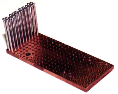
I started with a 5" by 2" by 1/4" piece
of copper C110 bar and bored about 240 holes to a depth of 3/16".
The diameter of the holes was a couple thousandths of an inch less than
the diameter of the aluminum pins that I would be installing into the holes.
Here I spent many hours boring different diameter holes to check the fit
of the pins. I then heated the copper bar and froze the aluminum
pins. This was to expand the holes and shrink the pins. One
by one the pins were forced into the holes. When the temperature
came back down to room temp, the objective was as tight of a fit as I could
get. After getting the sizes right, I found that I could get about
5 or 6 pins in before the base would cool off too much and would have to
be re-heated. Talk about tedium....
|
Installing the pins went on for what seemed
like weeks, but I finally got them all in. I knew that I wanted to
cut the heads off the pins to make the pin's profile a little smaller,
but I should have done the cutting before I installed the pins. I
ended up cutting the pins assembled into the sink on the band saw.
Not the easiest task, as the pins tended to vibrate and I had to insert
wooden wedges between the pins to keep them still. I wouldn't make
this mistake the next time.
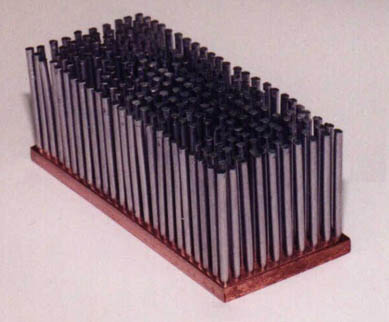
The pins are in and cut to length. |
To get some air moving through the pins,
I needed to add some fans. Fortunately, I HAD thought about that
before starting to build. The fan shroud that comes with the Alpha
P125 was the route I decided to take. I added a couple of 60mm, 12
volt, 3800 RPM, 25 CFM, Orion fans to the top and the usual array of temperature
sensors - 1 on the edge of the Celeron slug and 1 on the sink itself.
My trusty Aavid heat sink took its place as the backing plate to anchor
the Celeron in place without bending the circuit card.
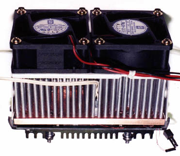
installed make for a busy looking package. |
Performance for the sink was good. It edged out the Alpha P125 is all categories, but not by any drastic margin. It did respond more quickly to the changes in temperature the Celeron goes through in a normal session though.
Even with this sink, my stubborn Celeron
still will not reliably run at 504 without additional cooling. Though
I will say that the longer I run the Cele at 504 with a peltier attached,
the easier it is to keep it at 504 without a TEC. Where I once couldn't
even boot into Windows at 504 without the extra cooling of the TEC, I can
now boot on most occasions and when I get lucky, even run a few tests.
But as usual, as soon as I stress it to any degree, it's lock up time.
in the 4 minute boot up test. That's cool! |
Because I can't measure the internal diode
temperature during boot up, the above CPU temperature is the reading taken
from the side of the Celeron's slug. From months of watching the
correlation of the slug temperature to the temperature of the thermal diode,
I have seen that the diode temperature can run as much as 25° F higher
than the slug for short periods of time. The slug temperature also
lags behind the diode temp by 10 seconds or so.
of the heat that the processor throws its way. |
I found, as I expected, that for non peltier applications, this thing is overkill. But that was not the reason I built it. So, it's time to throw a thermoelectric cooler on it and see what happens.
|
|
|
|