
|
|
|
Resistor installed |
Resistor not installed |
|
Serial #'s |
AHXXXXX, AIXXXXXX |
AH025584, AI013225 |
|
Serial #'s |
None |
AEXXXXXX, AFXXXXXX, AGXXXXXX. |
At this point, I do not know why the components - a 30k resistor and a .0033 µf (3300 pico farad) capacitor - were removed by Abit. There have been some reports that the temperatures were not as accurate as Abit had hoped for, so they dropped support for monitoring the internal diode.
It has been suggested that the problem may lie in the BIOS's ability to correctly read the diode. This may be correct, as with the circuit working and the CPU diode monitoring turned on in the BIOS (using Modbin), the temp reads too high (like many of the 3rd party temp reading programs). Note: Using Modbin to add the diode temperature into the BIOS has no effect on whether the temp can be read by third party software.
The thermal diode located on the CPU can be read with the W83782D Winbond chip. Abit follows Winbond's schematic and places the resistor and the capacitor as follows:
(From Winbond's Data Sheet)
The VREF is the Winbond reference voltage, GNDA is the analog ground, and T2 is the thermistor 2 input on the Winbond chip. The 0603 package size capacitor and resistor in this application have no orientation toward + or - voltage.
The component location on the BX6r2 is as follows:
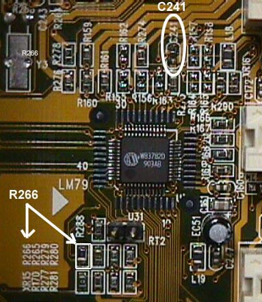 |
Now that you know where the resistor and capacitor need to be mounted, you need to be able to solder them in. The 0603 package size of these parts is so small that it makes for a pretty tough job. If you are not sure of your soldering skills or don't have a low or variable power soldering station, this may be a job best left to someone who is more familiar with the process. Someone at the local TV or computer repair shop may be able to do the work for you.
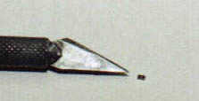
If you choose to do the work yourself, consider a way to hold the parts in place as you solder them. I used a dab of CA glue (modelers super glue) to hold the resistor and cap to the end of a paper clip so I could position it and hold it in place as I soldered. I read today that someone suggested actually using a small amount of CA to glue the resistor in place on the board and then solder it. I think I'd be worried about gluing it in the wrong position as CA sets on first contact and I don't have the steadiest of hands.
Another possibility is to use standard resistors and caps with leads. These can be had in similar values and because of their larger size, are easier to work with. I had some of these and soldered and tested them with the same results I got from the 0603 package size. While their larger size makes them easier to handle, it also make the finished product look like a hack instead of a stock board. The bottom line, though, is that - either way - you end up with a WORKING internal CPU thermometer.
Make sure that if you are going to attempt this that you follow the rules for grounding both yourself and the soldering iron. There is also no need to state that this "fix" will probably void your warranty. (-but I did anyway-)
Performance
I'm impressed. The fact that the
diode is inside the chip allows you to monitor the temperature as it happens.
There is very low thermal inertia to overcome with the measuring diode
so close to the heart of the CPU. My thermocouple mounted on the
processor's slug takes a few seconds before it registers any activity in
the chip. It is also removed from the interior of the chip enough
that I see more of an average of the chip's temperature than what happens
at the instant that 13 graphics and backgrounds all explode around my player
in Quake2. This is the time that without proper cooling, my system
would lock at 504. Having the ability to measure the temperature
inside the chip gives a much better picture of how much heat is actually
generated. I hope to learn more about cooling by charting the temps
in these situations.
Add the fact that there is some great temperature monitoring programs, like Motherboard Monitor, HMonitor, and MBProbe which will allow you to save a history of temperatures, and you have all the makings for a heat sink tester's dream-come-true.
Parts and Sources
The resistor needed is 30K Ohms with a
1% tolerance. Standard resistors are coded by colors with the first
2 bands being the numeric value, the third being the multiplier, and the
forth as the tolerance. The color code for a 1% 30K resistor would
be Orange - Black - Red - Brown. Surface mounted components use a
numbering system with the first and second digits as the numeric value,
and the third as the multiplier, so 30K would be 303. More
info on this can be found at: Cyber
Cow.
The needed capacitor has a value of 3300pf (.0033 µf). Capacitors are color coded in much the same way as resistors, but the colors cover more of the component (rather than thin color coded bands). The color and numeric codes may be found at the Cyber Cow.
Digi-Key is one of the many sources for electronic components on the net. Their part numbers for the 0603 packaged parts are P30KYCT-ND for the resistor and PCC332BVCT-ND for the cap. Use their parts search.
For a little larger parts, try these numbers:
30.1KXTR-ND for an axial lead 1/4 watt 30.1K resistor and
P4134-ND for a 1kV 3300pf (.0033 µf)
ceramic disc capacitor.
Thanks
Big thanks go to Darcel Tellis for the
great work on figuring out the solution to this problem. Thanks are
also in order for the confirmation work done by Mark Faust. Thanks
guys.
|
|
|