
|

an additional thermister in place. |
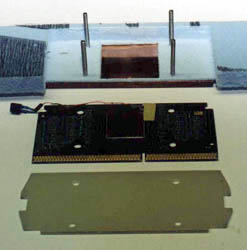
I started with another piece of exterior
insulation used for building houses and laid out a template for cutting.
If you are using a flat cold plate, and I was, the insulation between the
cold plate and the Celeron is pretty thin. This lack of insulation
was something I had been wondering about. Is it better to try to
cool the whole SEPP, or just the slug? Knowing what I do now, I would
have changed the cold plate so that there was a raised area to contact
the slug of the processor. But for this prototype, the plate remained
flat.
is put in place. |
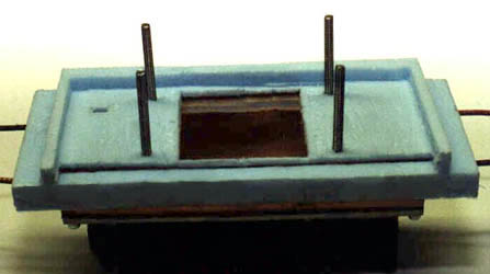
To attach the insulation for the SEPP to
the piece that surrounded the cold plate, I used some waterproof double
sided tape. I have used this automotive product for holding vapor
barriers on doors before, and it works great. Just don't plan on
separating the pieces without ruining them.
|
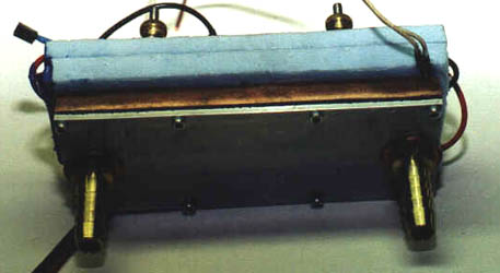
I added another 1/4" piece of insulation in behind the Celeron and attached the fiberglass backing plate. The whole assembly was held tight with helical springs and brass knurled thumbscrews. (These are visible at the top of the picture above.) I attached the water hoses, bled the air from the system, and plugged the assembly in to the board. The dual TECs were powered by a separate power supply from an old AT case.
Within a few minutes of running at 550
MHz, I knew I had a problem. I hadn't thought about the fact that
the thumbscrews and studs were attached directly to the cold plate.
These things were getting cold. Below zero Fahrenheit. Ice was forming
at a rapid rate. After 15 minutes, I had icicles. Not a good situation.
Back to the workshop.
|
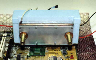
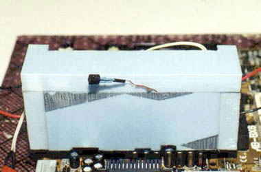
With a razor knife I removed the insulation
from the sides of the cooler and replaced it with pieces of 5/8" insulation
held in place by silicone sealer. The studs that held the assembly
together were shortened and the knurled thumbscrews were replaced by nylon
nuts. Another 5/8" piece of insulation was placed over the top of
the backing plate, again sealed with silicone. Finally, a cap of
more 5/8" insulation was fitted to the top. The insulation comes
with a thin, plastic sheet (it looks like Saran Wrap) covering it.
I made sure that any place there wasn't any of this vapor barrier, I applied
a thin coat of silicone sealer to try to make the whole assembly air-tight.
The bottom, where the SEPP fits into the socket is difficult to seal.
There isn't a lot of room to work with and still allow the edge connector
fit all of the way into the socket.
|
Back to the computer room and hook everything
up again. This time we're looking good (so I thought). After
an hour or so of running, there is no ice to be seen. Idle temperatures
are constantly at -20°F for the internal diode, sometimes going down
as low as -25. The water temperature is running about 2 to 3°F
higher than the room temp. I'm thinking success.
|
|
Over the course of the next couple of days,
I tested the setup. The best speed I could get from this Celeron
was 567 MHz (5.5 X 10³). Increasing the bus speed another 2 MHz to
105 or a total of 578 MHz would stop the processor from even booting into
the BIOS screen. I found this a bit strange because it was totally stable
at 567. I even tried letting the slug temperature get down
to -30°F before booting. Same thing, not even a beep from the
system. I doubt that heat played a part in this, as the difference
in temperatures between 550 MHz and 567 MHz were not measurable on the
equipment I have. I guess that I just hit the maximum speed of this processor.
|
If you follow my not too frequent updates on the news page, you will have figured out by now that this was the setup that killed my Abit BX6r2. The story of how it happened brings home the point that just because you can't see it, doesn't mean that it can't hurt you.
I had been working on the computer for most of the day. Mostly word processing. Because Word doesn't stress the system much, the temperatures had dropped very low. Everything was pretty cold. Even the motherboard around the slot one socket. I finished up on the work at hand and decided to work on some designs in AutoCad. AutoCad shuts down Rain as soon as it is started and the temperature of the processor increases accordingly. Apparently they system had gotten so cold that ice had formed inside the slot one socket. When the processor warmed up, so did the socket. Ice became water.
A little later, I decided to take a break for a while and shut the system down. As they say in the movies, "That was the last time it was ever seen alive." I got back on the computer a couple hours later to find that I couldn't complete the boot process. It would just hang at "Verifying DMI Data." After some initial troubleshooting, I pulled the processor to try another one in its place. Water literally dripped out of the socket. To make a long story short, I spent that night and the next day trying everything I could think of to get that board to run again. No success.
Since that time, I have purchased a new board to replace it - an Asus P3B-F this time. I've coated the entire board - both sides - in polyurethane, and have placed a 5/8" by 5/8" enclosure of insulation around the slot one socket. I have also filled the inside of the socket with Permatex dielectric grease. After about 3 weeks of constant use in all situations, I have yet to see ANY signs of moisture.
As I said at the beginning of this article, I've learned a lot from this last sink. Though I have now moved on to a PPGA Celeron and an adapter, if I were to refine this cooler another step, here's what I would change.
Reduce the size of the cold plate and raise the contact area (lower the rest of the plate) so that more insulation can go between the cold plate and the SEPP. Chilling the entire SEPP does nothing beneficial that I can see and it increases the chance of producing water in the socket. This cold plate was so big, that even with the dual TECs, it took about 5 minutes to chill down before I could start the computer. Too much mass.
Make the water cooler out of aluminum. With the number of water passages I had, cooling the TECs was not a problem. I am guessing (no, make that I know - as I am already running one) that aluminum will do the job with no problem. Aluminum is much easier to work with.
Find a way to make the whole processor enclosure air-tight. If moist air can be kept out, there will be no way for condensation to form. Don't laugh, but I've even been considering Tupperware.....
This ends the slot one heat sinks for a
while. If the 366 PPGA I just bought is an indicator, they seem to
be easier to get more speed out of. And for this guy, that's the
name of the game.