 |
The first thing I was presented with was that the base of the P125 is not one flat plane. It is thicker in the center where it attaches to the slug and thinner on both ends. While this "step" wouldn't matter if I attached the peltier directly to the sink, if I chose to use a "hot plate," this would not allow for full contact of the plate to the sink. In addition, the overall thickness of the base was also not as thick as the sinks I had recently been playing with. While I think that the thinner base allows for the heat to be transferred to the fins more quickly in a standard set up, I have had better results with a thick base when using a TEC.
I started testing with the P125 in stock configuration with the 30mm TEC and my standard 1/8" cold plate.

A big sink gets a little bigger with the addition
of the peltier, cold plate, and Aavid rear sink.
One modification that I did make was to re-drill and tap the mounting holes used with the Celeron. The P125 comes with two sets of holes. A larger diameter set for use with a spring clip and PII, and a smaller set which are drilled and tapped to accept 3mm metric screws. The 3mm screws were a bit on the thin side for the amount of items I was fastening together, so I tapped the holes to accept my standard 6-32 screws. This also allowed my helical springs and belville washers to fit correctly.
I had noticed that my usual between-the-fins placement of the heat sink thermometer probe was not going to be possible on this sink due to the close spacing of the fins. I opted to slightly enlarge one of the PII mounting holes and mount the tubing encased thermistor there. I got a nice snug fit by using a little heat sink compound. This has turned out to be a good idea, as the location of the probe will not change and the readings will be true for each different configuration of the sink.
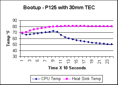
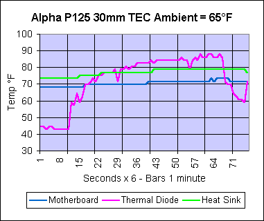
Performance with 30mm TEC
Using the same tests as I did for the
sink with no TEC, the results are as follows:
 |

The Q2 demo test at 504 MHz. The internal diode is reading a
little high for a room temperature of only 65°F.
At 65°F the P125 and TEC perform acceptably, but with the internal temperature of the chip approaching 90° on just a couple of Q2 demos, this combination probably won't cut it with higher room temperatures. A larger cold plate and / or a bigger TEC might help lower the chip's temp. By the look of the heat sink's temp, it might take more heat than I threw at it in this test. We'll see.
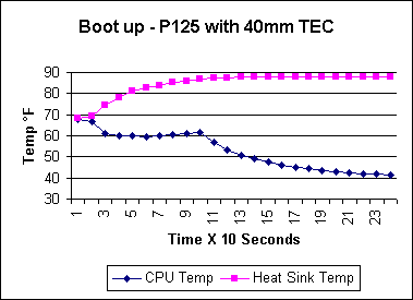
Performance with 40mm TEC
The next step was to install the 40mm
TEC. Again, like the 30mm, this peltier was sandwiched between the
1/8" cold plate and the P125 sink. No additional hot plate was used.

The additional cooling of the 40mm TEC is not without its price.
While the slug runs about 8°F cooler, the P125 runs about 8°
warmer.

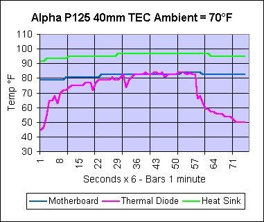
There is not a great deal of difference between the 30 and 40mm TECs
in the Quake test -- as far as the internal diode is concerned, anyway.
Notice that unlike the 30mm TEC, the diode temp has stabilized quickly.
The 40mm TEC is a step in the right direction for the CPU temp, with the chip's temp dropping over 5°F while the room temperature was up by 5°F. Condensation has not been a problem at this stage in the testing, though with the idle temperatures into the 30's, I suspect it will become a problem soon.
|
|
|
|