 |

Problems and some solutions
I could document the day by day testing
I did with this cooler, and would, but it would take an additional dozen
pages and is really pretty dry reading. I decided that it was better
to just list the problems and how I attempted to solve them.
Assuming that the TECs would not operate at their 6 amp rated draw, but thinking that the three of them would still be too much for my 12 amp rated AT power supply, I split 2 of the TECs to the 12 amp AT supply and the one remaining TEC to a 10 amp supply. I tested the setup to find that the coldest temp it could reach was -10°F on the cold plate and +10 for the internal diode. This was with a room temperature of about 75°F (25°C). Very disappointing to say the least.
First I was concerned about the poor cold plate temperature. I checked the voltage and amperage for the TECs and found that the 2 TECs were only drawing a total of 5.6 amps together (wired in parallel) and this brought the power supply voltage down to 10.5 volts. Not good. Trying the 5 different AT style supplies I have, the readings remained the same. I received similar results from a 15 amp automotive battery charger (a cheap unit...).
Wondering about the results, I tested the
two 30 mm peltiers I had used in WC4. These are SNOWBALL-71's
from TE Distributing and are rated at a max of 3.9 amps, 36 watts at 16.1
volts. These two, again wired in parallel, drew 6 amps at 11.0 volts.
Strange. Well, I needed a new power supply anyway. The home-built
20 amp, 13.7 volt unit I had used for bench testing and NiCad charging
had finally died after 10 years of rough use. I decided to go with
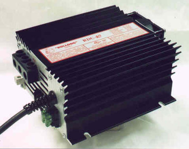
a brand I knew from my days of racing RC cars and got a Rivergate
Bulldog 30 amp. This is one hefty supply and I have seen many
of them go through hell without failing.
 |
With the new power supply hooked up, the two 40 mm TECs went up to 6 amps at 12.5 volts. The three TECs pulled 8.8 amps at 12.5 volts. This was an improvement, but testing the two 30 mm TECs revealed that they pulled 7.8 amps at 12.5 volts. The fact that the two 30's pulled more amperage than the two 40's, in itself, doesn't mean a whole lot. However, actual temperature testing on the bench showed that the two 30's outperformed the two 40's. This almost brought the project to a standstill. However, I figured I had come this far and might as well see how cold I could get this cooler.
Re-assembling WC7, I tried again. - Yes, I stripped it down. One of many times. I had to make sure that I had good thermal contact on both sides of the peltiers. - This time, the cold plate got down to -17°F. Better, but nothing to rave about. To make matters more confusing, the internal processor temperature was running at between +7 and -5° when the cold plate was running at -17°. This was using Rain.
I have been playing with heat sinks for long enough that I am pretty used to the normal results I get. Running a software cooler (Rain, CPUIdle, whatever) and letting the processor sit idle, the internal temperature usually runs very close to the heat sink or cold plate temperature. Getting such a difference in temperature between the cold plate and the internal temp was baffling me.
Five more times I took the cooler apart. Each time with the same result. I had picked up a Celeron 2 - 533 and another Iwill Slotket2 to play with and noticed the same phenomenon with it. Both water cooled and using a stock P3 Intel heat sink. I decided to start eliminating possibilities by making sure that I was getting good thermal contact on the wafer of the processor. I have tested no less than 10 different designs for shims to make sure that the heat sink or cold plate sits squarely on the processor. Some worked better than others, but I never got the internal temperature to where I thought it should be.
It wasn't until much later that I came across a possible reason. I had picked up an Abit SlotKET III to play with because it doesn't have the 5 tall capacitors that make designing a large cold plate a chore. I threw the Celeron 2 on it with a stock heat sink. At idle, the temp of the heat sink and internal processor temperature would settle within a degree or two of each other. So much for beating my head against the wall for a few weeks trying to figure out the reason for the temperature difference. The Iwill adapter seems to give me high internal readings with my Asus P3-BF board. As I am not quite ready to drop the Celeron2 or P3 into my Linux box that uses an Abit BX6r2, I don't know if the problem lies with the Iwill adapter or the combination of the Iwill and the Asus board. However, 2 Iwill adapters give the same result with the P3-BF.
Not to get too far off on tangents, but
in keeping with measuring internal processor temperatures on the P3-BF
board, there seems to be a problem with the way my board (or maybe the
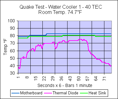
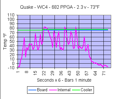
Asus boards in general) read the thermal diode temperature. I noticed
that when I switched from the Abit BX6r2 (modified
to read the internal diode temp) to the P3-BF, the temperature "pattern"
changed. Where the Abit read the temperatures predictably increasing
or decreasing depending on the processor load, the Asus readings jumped
up and down.
 |
 |
I have lived with the situation and have gotten used to looking at the results of the Asus board as an average, reading the curve, rather than as the absolute set of temperatures. I hadn't seen much of anything posted about this situation and didn't give it to much thought until I read an article at Overclockers.Com titled "ASUS P3V4x’s False Temperature Readings." Included with the author's adventures with trying to read his internal temps was this quote. "Everything is fine now although I still get some small and crazy temperature jumps from 40 to 45 to 41, 46, 44, 43, 46 (MB temperature polling interval=1 sec!!!!). "
I guess that I'm not the only one.
Results
With WC7 now getting down to -17°F
I hoped to be able to crack the 933 MHz barrier with this P3-700.
Alas, this chip will do 868 MHz at stock voltage with the boxed Intel heat
sink and will not go further. I have tried from 1.55 volts to 1.90.
I have tried adding ice into the water cooler setup and getting the booting
temperature of the processor down to -35°F. I can't get so much
as a full bootup. Trying a second P3-700 that would only do 805 with
the stock sink, cooling the chip to only the 50°F mark would get 868, but
no further by going to -35°. For the record, neither of these chips were the cB0 stepping.
Now, the Celeron2-533, that is another story to tell!
Conclusions
I have come to 3 conclusions after this
project. One is that I'm not impressed with the Melcor PT6-12-40
TECs at all. I put WC4 back together with its two TE peltiers and
with the increased amperage that the Rivergate supplies, I was able to
get the cold plate temperature down to -25°F in a 75° room.
No ice needed. I also do not like using such a large cold plate and
multiple peltiers. There's just too much surface area to deal with.
It's hard to get the proper contact on all three TECs at the same time.
The thickness of the thermal paste becomes critical and there's no good
way to check the contact without taking the unit back apart. Of course,
that means starting over again. Third, and last, sometimes chillin'
the chip just doesn't help. While 868 from a 700 P3 is not much of
an overclock, running 868 straight out of the box with no additional cooling
is not exactly slow. It's just not what I had hoped for.
WC8 is already in the testing phase.
This time I took the opposite approach. One TEC and a small profile
water block. It is already hitting temperatures in the -36° F
zone. The Celeron2 seems to like this. Oh, did I mention that
the TEC is rated at (max) 11.3 amps, 111.0 Watts at 15.9 volts....
Nice.
|
|
|
|
|