 |
Second, I needed some way to raise or regulate the low temperature achieved at idle. Not only was I worried about frost and condensation, but I hoped to reduce the swing in temperature from almost freezing to the 90°F range is less than a couple minutes. The accepted method for regulating temperature for peltiers is with a electronic circuit designed to vary the current to the TEC depending on temperature. There are many circuit designs available for this and I may get around to building such a controller, but for now I was looking for a simpler method. I was also looking for a way to increase the cooled mass so that when the processor was stressed, there would be a "reserve of cold" to draw from to lessen the temperature swings. I settled on a mechanical means of accomplishing this.
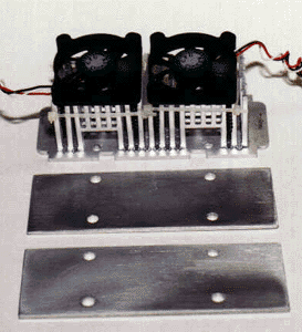
I began by using a pin-type heat sink made by Fullway that I had in my parts box. This no-fan heat sink has a mass of about 5 ounces and a surface area of about 110 sq. in. It performed pretty well in my heat sink tests considering it used no fan. During the tests, I thought it would been great with a couple of fans added to it. I used the heat sink base as a template and traced and cut two pieces of 1/8" sheet aluminum, one to be used to increase the mass of the heat sink and one to be used for "cold storage" for the processor. These aluminum plates were fairly flat and smooth to begin with, but I spent another couple of hours per plate lapping them with progressively finer grades of sandpaper until I ended up using 1000 grit paper for the final polishing. Each one of these plates adds about one ounce and 25 sq. in. of surface area to the sink. With all surfaces as flat and smooth as I could get them, I began assembly.

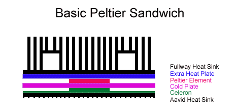
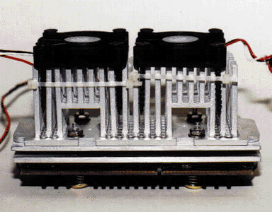
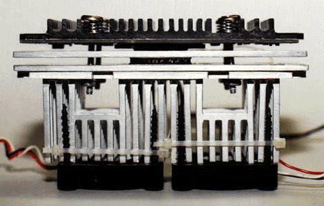
The peltier heat sink assembly was assembled by stacking the components as shown, sandwich style. A thin layer of heat sink compound was used between each piece. The exception was between the Celeron and the Aavid heat sink, which was insulated with duct tape so as not to short circuit the Celeron.

The whole assembly was held together with 4 -1½" 6-32 screws and nuts, with springs used so that equal force would be applied on the processor.
 .
.
Adding the fans to this prototype was a
mickey-mouse arrangement at best. The lack of thickness of the heat
sink's pins prevented drilling them to accept screws, and there wasn't
enough room between the pins to add stand-offs. My temporary solution
works and the fans are not in any danger of falling off, but it looks like
I don't know which end of a hammer to hit myself with.
|
Intro . |
voltage limits |
high volts |
trying peltiers |
second attempt |
stable @ 504 |
lower voltage |
case heat |
final thoughts |
build it |